
Datasheet


Push Buttons and Switches
2-10 ADSP-21479 EZ-Board Evaluation System Manual
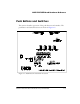
Boot Mode Select Switch (SW4)
The boot mode select switch (SW4) determines the boot mode of the pro-
cessor. Table 2-7 shows the available boot mode settings. By default, the
processor boots from the on-board parallel flash memory.
The selected position of
SW4 is marked by the notch down the entire rotat-
ing portion of the switch, not the small arrow.
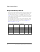
DSP Clock Configuration Switch (SW5)
The clock configuration switch (SW5) controls the core frequency of the
processor at power up. The core to clock-in ratio is multiplied by the
16.625 MHz oscillator (
U42) to produce the power up core frequency.
Table 2-8 shows the switch settings.
The core clock frequency can be increased or decreased via software by
writing to the PMCTL register. For more information on changing the core
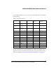
Table 2-7. Boot Mode Select Switch (SW4)
SW4 Position Processor Boot Mode
0 SPI slave boot
1 Boot from SPI flash memory (SPI master boot)
2 Boot from 8-bit external parallel flash memory (default)
3 Reserved
4 Reserved
5 Reserved
6 Reserved
7 Reserved