
Datasheet


ADSP-21479 EZ-Board Evaluation System Manual 2-11
ADSP-21479 EZ-Board Hardware Reference
clock frequency and other settings, refer to the ADSP-214xx SHARC Pro-
cessor Hardware Reference.
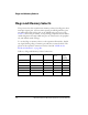
DAI [17–20] Enable Switch (SW7)
The DAI [17–20] enable switch (SW7) disconnects DAI pins 17 through
20 on the processor from the associated peripherals on the EZ-Board and
allows the DAI signals to be used on the expansion II interface. See
Table 2-9.
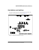
Programmable Flag Push Buttons (SW8–11)
Four momentary push buttons (SW8–11) are provided for general-purpose
user input. The buttons are connected to the GPIO pins of the processor.
The push buttons are active high and, when pressed, send a high (1) to the
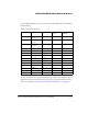
Table 2-8. Processor Clock Configuration Switch (SW5)
Position 1
CLKCFG0
Position 2
CLKCFG0
Clock Ratio
Core: Clock
ON ON Reserved
ON OFF 32:1
OFF ON 16:1 (default)
OFF OFF 8:1
Table 2-9. DAI [17–20] Enable Switch (SW7)
SW7 Position DAI Pin Peripheral Peripheral Net Switch Setting
(Default)
SW7.1 DAI_P17 LEDs LED8 ON
SW7.2 DAI_P18
S/PDIF SPDIF_IN ON
SW7.3 DAI_P19 Push buttons PB3 ON
SW7.4 DAI_P20
Push buttons PB4 ON