
Datasheet


ADSP-21479 EZ-Board Evaluation System Manual 2-13
ADSP-21479 EZ-Board Hardware Reference
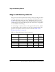
respective control signals to be used on the expansion II interface. See
Table 2-10.
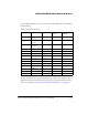
DPI [9–14] Enable Switch (SW14)
The DPI [9–14] enable switch (SW14) disconnects DPI pins nine through
14 on the processors from the associated peripherals on the EZ-Board and
allows the DPI signals to be used on the expansion II interface. See
Table 2-11.
Table 2-10. External Port Enable Switch (SW13)
SW13
Position
Processor Pin Peripheral Peripheral Net Switch Setting
(Default)
SW13.1 MS0 SDRAM SDRAM_CS ON
SW13.2 MS1 Parallel flash
memory
FLASH_CS ON
SW13.3 FLAG1/IRQ1 Push buttons PB1 ON
SW13.4 FLAG2/IRQ2/MS2 Push buttons PB2 ON
SW13.5 FLAG3/MS3 SRAM SRAM_CS ON
SW13.6 WDTRSTO (Watch Dog
Rest Out)
Reset Supervi-
sory IC
WDTRSTO OFF
Table 2-11. DPI [9–14] Enable Switch (SW14)
SW14
Position
DPI Pin Peripheral Peripheral Net Switch Setting
(Default)
SW14.1 DPI_P9 UART UART_TX ON
SW14.2 DPI_P10
UART UART_RX ON
SW14.3 DPI_P11
UART UART_RTS OFF
SW14.4 DPI_P12 UART UART_CTS OFF
SW14.5 DPI_P13
LEDs LED2 ON
SW14.6 DPI_P14
LEDs LED3 ON