
Datasheet


Push Buttons and Switches
2-16 ADSP-21479 EZ-Board Evaluation System Manual
Audio In2 Left Selection Switch (SW18)
The audio selection switch (SW18) connects the left channel of the In2 line,
connected to the AD1939’s ADC3 circuit, to either the single-ended RCA
connectors or the differential DB25 connector. By default, the switch is
set up to use the RCA connectors for audio in. To use the standard, off
the shelf DB25 connector to XLR cables, change the switch to the differ-
ential setting. See Table 2-15. For more information, see “Differential
In/Out Connectors (P8–9)” on page 2-28.
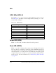
JTAG Switches (SW19–22)
The JTAG switches (SW19, SW20, SW21, and SW22) select between a sin-
gle-processor (one EZ-Board) and multi-processor (more than one
EZ-Board) configurations. By default, the four DIP switches are set up for
a single EZ-Board configuration. See Table 2-16.
The default configuration applies to either a debug agent or an external
emulator, such as the Analog Devices high-performance USB-based emu-
lator (HP-USB ICE for short). To use an external emulator and multiple
EZ-Boards simultaneously in one VisualDSP++ multi-processor session,
set up the boards as shown in Table 2-17. Attach the boards to each other
via connectors J3 and P10. For two EZ-Boards, no external cables are
required. For three or more EZ-Boards, obtain Samtec JTAG cables
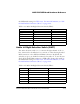
Table 2-15. Audio In2 Left Selection Switch (SW18)
SW18 Position Single Ended RCA IN (Default) Differential DB25 IN (P8)
SW18.1 ON OFF
SW18.2 OFF ON
SW18.3 ON OFF
SW18.4 OFF ON
SW18.5 ON OFF
SW18.6 OFF ON