
Datasheet


Jumpers
2-20 ADSP-21479 EZ-Board Evaluation System Manual
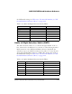
Flash WP Jumper (JP1)
The flash WP jumper (JP1) write-protects block 0 of the parallel flash
chip. Block 0 is located at address range 0x0400 0000–0x0400 1FFF. The
POST begins at block 0 and continues on to other blocks in flash mem-
ory. When the jumper is installed on JP1, and the parallel flash driver
from Analog Devices is used, block 0 is read-only. By default, JP1 is not
installed.
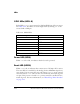
S/PDIF Loopback Jumper (JP2)
The S/PDIF loop back jumper (JP2) is used for internal testing only. The
jumper loops back any digital audio signal from the S/PDIF’s Data Out
pin to the S/PDIF’s Data In pin. By default, JP2 is not installed.
UART RTS/CTS Jumper (JP3)
The UART RTS/CTS jumper (JP3) connects the RTS and CTS pins of the
RS-232 interface. By default, JP3 is installed.
UART Loopback Jumper (JP4)
The UART loop back jumper (JP4) is used for internal testing only. The
jumper loops back UART receive data from UART transmit data. By
default,
JP4 is not installed.
DSP Audio Oscillator Jumper (JP5)
The processor audio oscillator jumper (JP5) connects a 24.576 MHz
oscillator to the
DAI_P17 pin of the processor. The jumper can be used to
make the processor the master and the AD1939 device—the slave. By
default,
JP5 is not installed, resulting in the AD1939 being the master,
and the processor being the slave.