
Datasheet


LEDs
2-22 ADSP-21479 EZ-Board Evaluation System Manual
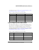
GPIO LEDs (LED1–8)
Eight LEDs (LED1–8) are connected to DAI and DPI pins of the processor.
See Table 2-18. The LEDs are active high and lit by writing a ‘1’ to the
correct DAI or DPI pin.
Power LED (LED9)
When LED9 is lit solid, it indicates that the board is powered.
Reset LED (LED10)
When LED10 is lit, it indicates that a master reset of all major ICs is active.
The reset LED is controlled by the Analog Devices ADM708 supervisory
reset circuit. You can assert the reset push button (SW12) to assert a master
reset and activate LED10. The reset also is controlled by the watch dog reset
out pin of the processor. Switch
SW13 position 8 must be enabled for the
watch dog reset. For more information, see “Watch Dog Timer Interface”
on page 1-12.
Table 2-18. GPIO LEDs
LED Reference Designator Processor Pin
LED1 DPI_P6
LED2 DPI_P13
LED3 DPI_14
LED4 DAI_P3
LED5 DAI_P4
LED6 DAI_P15
LED7 DAI_P16
LED8 DAI_P17