
Datasheet

EVAL-AD5243SDZ User Guide UG-346
Rev. 0 | Page 5 of 16
Signal Amplifier
RDAC2 can be operated as an inverting or noninverting signal
amplifier supporting linear or pseudologarithmic gains. Table 6
shows the available configurations.
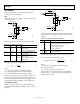
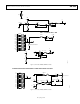
The noninverting amplifier with linear gain is shown in Figure 4,
and the gain is defined in Equation 3.
R38
R
G
WB2
+=1
(3)
V
IN
RDAC2
B2A2
R42
W2
B2
W2
V
OUT
OAVOUT
A2
C1
10nF
R41
1.7kΩ
R43
10364-005
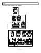
Figure 5. Pseudologarithmic Noninverting Amplifier
R43 and R42 can be used to set the maximum and minimum
gain limits.
where
R
WB2
is the resistor between the W2 and B2 terminals.
V
IN
RDAC2
B2
R42
W2
B2
W2
V
OUT
OAVOUT
C1
10nF
R41
1.7kΩ
R38
2.7kΩ
10364-004
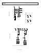
The inverting amplifier with linear gain is shown in Figure 6,
and the gain is defined in Equation 5.
Note that the input signal, V
IN
, must be negative.
R38
R
G
WB2
−=
(5)
where
R
WB2
is the resistor between the W2 and B2 terminals.
Figure 4. Linear Noninverting Amplifier
V
IN
RDAC2
B2
R42
W2
B2
W2
V
OUT
OAVOUT
C1
10nF
R41
1.7kΩ
R38
2.7kΩ
10364-006
The noninverting amplifier with pseudologarithmic gain is
shown in Figure 5, and the gain is defined in Equation 4.
AW2
WB2
R
R
G += 1 (4)
where:
R
WB2
is the resistor between the W2 and B2 terminals.
R
AW 2
is the resistor between the A2 and W2 terminals.
Figure 6. Linear Inverting Amplifier
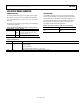
Table 6. Amplifier Selection Link Options
Amplifier Gain Link Label V
IN
Range
Noninverting Linear A27 LINEAR 0 V to V
DD
A29 NON-INV
A30 NON-INV
Pseudologarithmic A27 PSEUDOLOG 0 V to V
DD
A29 NON-INV
A30 NON-INV
Inverting Linear A27 LINEAR −V
DD
to 0 V
A29 INV
A30 INV