MODEL: OFX803 MODEL: OFD803 MODEL: OCP803 MODEL: QFX402 User’s Manual ANALOG WAY® OCTO² / QFX402 EDITION : 11 / 06
OCTO² / QFX402 TABLE OF CONTENTS SAFETY INSTRUCTIONS ...........................................................................................................................................................3 QUICK START GUIDE - OCTO2 .................................................................................................................................................6 QUICK START GUIDE - QUATTRO FX..................................................................................................
OCTO² / QFX402 SAFETY INSTRUCTIONS All of the safety and operating instructions should be read before the product is operated and should be retained for further reference. Please follow all of the warnings on this product and its operating instructions. CAUTION: WARNING: To prevent the risk of electric shock and fire, do not expose this device to rain, humidity or intense heat sources (such as heaters or direct sunlight).
OCTO² / QFX402 INSTRUCTIONS DE SÉCURITÉ Afin de mieux comprendre le fonctionnement de cet appareil nous vous conseillons de bien lire toutes les consignes de sécurité et de fonctionnement de l’appareil avant utilisation. Conserver les instructions de sécurité et de fonctionnement afin de pouvoir les consulter ultérieurement. Respecter toutes les consignes marquées dans la documentation, sur le produit et sur ce document.
OCTO² / QFX402 SICHERHEITSHINWEISE Um den Betrieb dieses Geräts zu verstehen, raten wir Ihnen vor der Inbetriebnahme alle Sicherheits- und Betriebsanweisungen genau zu lesen. Diese Sicherheits- und Betriebsanweisungen für einen späteren Gebrauch sicher aufbewahren. Alle in den Unterlagen, an dem Gerät und hier angegebenen Sicherheitsanweisungen einhalten.
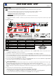
QUICK START GUIDE - OCTO2 ANALOG WAY EDITION : 11/06 CONNECTIONS: NOTE: Turn OFF all of your equipment before connecting. c Connect the AC power supply cord to the OFX803 / OFD803 / OCP803 and to an AC power outlet. d Connect your computer & video sources to the 8 universal inputs of the OFX803 / OFD803 / OCP803. • If you need to connect a digital computer source, use the input #1 (DVI-I IN connector). • Connect your others sources to the unused inputs. IMPORTANT: Connect only one source by input.
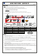
QUICK START GUIDE - QUATTRO FX ANALOG WAY EDITION : 11/06 CONNECTIONS: NOTE: Turn OFF all of your equipment before connecting. c Connect the AC power supply cord to the QFX402 and to an AC power outlet. d Connect your computer & video sources to the 4 universal inputs of the QFX402. • If you need to connect a digital computer source, use the input #1 (DVI-I IN connector). • Connect your others sources to the unused inputs. IMPORTANT: Connect only one source by input.
OCTO² / QFX402 OCTO-FX² / OCTO-FADE² / OCTO-PLUS² / QUATTRO FX Chapter 1 : INTRODUCTION 1-1. ACCESSORIES SUPPLIED • • • • • • • • 1 OCTO-FX² (OFX803) or 1 OCTO-FADE² (OFD803) or 1 OCTO-PLUS² (OCP803) or 1 QUATTRO FX (QFX402). 1 AC Power supply cord. 1 HD15 male / 5xBNC female cable adaptor. 1 HD15 female / DVI-I male adaptor. 1 Set of 5 MCO (5-pin) female connectors (OFX803, OFD803 & OCP803). 1 Set of 3 MCO (5-pin) female connectors (QFX402). 1 CD-ROM (Remote Control Software). 1 User’s Manual. 1-2.
OCTO² / QFX402 Chapter 1 : INTRODUCTION (continued) 1-3. QUATTRO FX GENERAL INFORMATION QUATTRO FX by Analog Way is High Resolution Digital and Analog Computer & Video Up/Down Scaler Switcher. It features many other effects: fading & titling, Hi-Res. logo insertion and frame store. It is fitted with 4 Universal A/V inputs including one DVI, and 2 outputs: 1 Analog and 1 DVI. It performs an ultra fast and smooth transition between any Video or Computer sources.
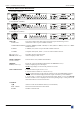
OCTO² / QFX402 Chapter 1 : INTRODUCTION (continued) 1-6. OCTO² FRONT PANEL DESCRIPTION • OCTO-FX² (OFX803) ANALOG WAY • OCTO-FADE² (OFD803) ANALOG WAY • OCTO-PLUS² (OCP803) ANALOG WAY INPUT #8: AUDIO L+R: Universal (computer and video) input. This input accepts the following sources: Audio stereo source on jack 3.5 female connector. COMPUTER/TV/HDTV: Computer (RGBHV, RGBS or RGsB) or video (SDTV or HDTV) source on a HD15 female connector. S.VIDEO: S.
OCTO² / QFX402 Chapter 1 : INTRODUCTION (continued) 1-7. QUATTRO-FX FRONT PANEL DESCRIPTION ANALOG WAY Fn: Secondary function selection button. EFFECT PRESET : Selection of the CUT, FADE & TITLE effects. INPUT SELECTION: • Selection of the 4 input sources: 1 to 4. • Selection of the 4 frames: F1 to F4. NOTE: -Frame selection can be used only when Fn is activate (LED blinking quickly). -The source/frame displayed onto the output is indicate by a turn ON LED.
OCTO² / QFX402 Chapter 1 : INTRODUCTION (continued) 1-8. OCTO² REAR PANEL DESCRIPTION 100-250 VAC, 1A, 50-60 Hz: AC power inlet. O / I: AC power switch (O = OFF, I = ON). IP/LAN: LAN communication port on a RJ45 connector (optional). RS-232: RS-232 communication port on a DB9 female connector. 7 UNIVERSAL COMPUTER & TV/HDTV INPUTS: 1: Universal (computer and video) input on a DVI-I female connector. NOTE: This input accept analog & digital Computer source.
OCTO² / QFX402 Chapter 1 : INTRODUCTION (continued) 1-9. QUATTRO FX REAR PANEL DESCRIPTION 100-250 VAC, 1A, 50-60 Hz: AC power inlet. O / I: AC power switch (O = OFF, I = ON). IP/LAN: LAN communication port on a RJ45 connector (optional). RS-232: RS-232 communication port on a DB9 female connector. 4 UNIVERSAL COMPUTER & TV/HDTV INPUTS: 1: Universal (computer and video) input on a DVI-I female connector. NOTE: This input accept analog & digital Computer source.
OCTO² / QFX402 Chapter 2 : STARTING 2-1. OCTO² CONNECTIONS NOTE: Turn OFF all of your equipment before connecting. c Connect the AC power supply cord to the device and to an AC power outlet. d Connect your computer & video sources to the 8 universal inputs of the device. • If you need to connect a digital computer source, use the input #1 (DVI-I IN connector). • Connect your others sources to the unused inputs. See following sections to have a complete description.
OCTO² / QFX402 Chapter 2 : STARTING (continued) 2-3. INPUT #1 DESCRIPTION c CONNECTION: You can connect to this input one of the following source: • A composite video source. • A S.VIDEO source. • A Component video source (YUV). • A HD-YUV source. • A RGBS video source. • An analog (RGBHV, RGsB, RGBS) computer source. NOTE: You can use the DVI / HD15 adaptor provided with the device to connect analog sources on the DVI-I (IN) connector. • A digital computer source.
OCTO² / QFX402 Chapter 2 : STARTING (continued) 2-4. INPUTS #2 to 8 DESCRIPTION c CONNECTION: You can connect to these inputs one of the following source: • A composite video source. NOTE: The input #7 can accept a composite video source on its BNC connector. The input #8 can accept a composite video source on its RCA connector. • A S.VIDEO source. NOTE: The input #7 can accept a S.VIDEO source on its BNC connectors. The input #8 can accept a S.VIDEO source on its 4-pin mini DIN connector.
OCTO² / QFX402 Chapter 2 : STARTING (continued) 2-5. OUTPUTS DESCRIPTION (continued) f DVI-I PIN ASSIGNMENT (QFX402 only): Pin Function Pin Function 1 2 3 4 5 6 7 8 C1 C2 C3 C4 C5 TMDS Data 2TMDS Data 2+ TMDS Data 2 Shield Not used. Not used. DDC Clock DDC Data Analog Vertical Sync. Not used Not used Not used Not used Not used 9 10 11 12 13 14 15 16 Pin TMDS Data 1TMDS Data 1+ TMDS Data 1 Shield Not used. Not used. + 5V (Power) Ground for (+5V) Hot plug detect. DDC = Display Data Channel.
Chapter 2 : STARTING (continued) OCTO² / QFX402 2-6. AUDIO INPUTS (continued) • MCO male connector (OFX803, OFD803, OCP803) The INPUTS # 3 to 7 & AUX are equipped with this connector. Connect your audio sources as follow: -Inputs # 3, 4, 5, & 6: Unbalanced connection only. -Inputs # 7 & AUX: Balanced & unbalanced connection. • MCO male connector (QFX402) The INPUTS # 2 to 4 are equipped with this connector. Connect your audio sources as follow: -Inputs # 2 & 3: Unbalanced connection only.
OCTO² / QFX402 Chapter 3 : OPERATING MODE The device can be used in two different switching modes. • The SEAMLESS MODE, allows switching seamlessly, fading* and titling* between the "reference" COMPUTER input and the others inputs. These ones are scaled to the same format as the "reference" COMPUTER format. NOTE: The inputs, which can be used as the "reference" Computer input, are the Input # 1 and # 8. NOTE: The "reference" Computer is not scaled.
OCTO² / QFX402 Chapter 3 : OPERATING MODE (continued) 3-2. SWITCHING OPERATIONS -The device allow switching between its inputs with 4 different effects: CUT, FADE*, FADE COLOR and CLEAN CUT. The CUT effect allows switching seamlessly between 2 sources. The FADE effect allows fading out the displayed source while another source is fading in. The FADE COLOR effect allows switching between 2 sources with a fading to a customized color.
OCTO² / QFX402 Chapter 3 : OPERATING MODE (continued) 3-2. SWITCHING OPERATIONS (continued) • FADE COLOR: The FADE COLOR allows switching between 2 sources with a fading to a color of you choice. This transition operates in Fast Switching mode and sometimes in Seamless mode (only when the others effects are not possible). You can select the color of the fading with the LCD menu (CONTROLS > Transition > Fade color).
OCTO² / QFX402 Chapter 4 : USING FRAME STORE AND LOGO INSERTION These functions are only available with the OFX803 & QFX402. 4-1. LOGO INSERTION This function allows storing up to 8 static logos & 1 animated logo in order to incrust them into the displayed image (up to 2 logos at the same time). IMPORTANT: The output format used when displaying logo should be the same that the output format used during the logo storing.
OCTO² / QFX402 Chapter 4 : USING FRAME STORE AND LOGO INSERTION 4-2. USING THE FRAME STORE This function allows memorizing up to 4 frames (images) in order to display it at any time during the show. IMPORTANT: The output format used when displaying the frame should be the same that the output format used during the FRAME storing. • HOW TO STORE A FRAME: c Select the source of the frame to be stored (with the INPUT SELECTION buttons).
OCTO² / QFX402 Chapter 5 : FRONT PANEL DISPLAY MENUS DESCRIPTION 5-1. INTRODUCTION The front panel display menu presents 2 modes: the STATUS MODE and the CONTROL MODE. • The STATUS MODE indicates the input and output status of the device. • The CONTROL MODE allows selecting and adjusting the parameters of the device. 5-2. CONTROL BUTTONS The front panel display is controlled by 2 buttons and 1 knob: • In the CONTROL MODE, turn this knob to scroll thru the different menus.
OCTO² / QFX402 Chapter 5 : FRONT PANEL DISPLAY MENUS DESCRIPTION (continued) 5-4. CONTROL MODE The menus of the CONTROL MODE are configured as follow: 1 SWITCHING 2 INPUT 1 Fast switching Output rate [ internal ] [ follow #1 ] ….. [ follow #8 ] 2 Seamless Seamless [ seamless #1 ] [ seamless #8 ] 1 Auto-setting 2 Input status 3 OUTPUT 3 Input type 1 #1 Comp. HV/C 2 #2 Comp. HV/C 3 #3 Comp. HV/C 4 #4 Comp. HV/C 5 #5 Comp. HV/C 6 #6 Comp. HV/C 7 #7 Comp. HV/C 8 #8 Comp.
OCTO² / QFX402 Chapter 5 : FRONT PANEL DISPLAY MENUS DESCRIPTION (continued) 5-4. CONTROL MODE (continued) 5 LOGOS/FRAME* 1 Use logo 1 Display 1 Input #1 ON …………… 8 Input # 8 OFF 2 Assignment 1 All inputs 2 Input # 1 …………… 9 Input # 8 3 Positions 4 Transparency 5 Fade duration 2 Record logo 3 Record anim 4 Record frame 5 Erase logo 6 Erase frame 6 EFFECT** 3 Key 3 : Fading Index 1 Index 2 Logo 2 none 1 H.position 2 V.
OCTO² / QFX402 Chapter 5 : FRONT PANEL DISPLAY MENUS DESCRIPTION (continued) 5-5. FUNCTIONS DESCRIPTION 1 [SWITCHING] + ENTER. 1-1 [Fast switching] + ENTER. Select an item with + ENTER. • [Internal rate]: The output frame rate is 60 Hz or 75 Hz depending of the selected output format. A higher frame frequency gives a better visual aspect when displaying static pictures.
Chapter 5 : FRONT PANEL DISPLAY MENUS DESCRIPTION (continued) 3 OCTO² / QFX402 [OUTPUT] + ENTER. 3-1 [Output status] + ENTER. Indicates the status of the output. 3-2 [Output format] + ENTER. Select one of the available output formats with + ENTER.
OCTO² / QFX402 Chapter 5 : FRONT PANEL DISPLAY MENUS DESCRIPTION (continued) 4 [IMAGE] + ENTER. • If the selected input type is a VIDEO signal the IMAGE MENU displays the following items: 4-1 [Pos. settings] + ENTER. Select one of the following functions with + ENTER. 4-1-1 [H position] + ENTER. Adjust the Horizontal position with + ENTER. 4-1-2 [V position] + ENTER. Adjust the Vertical position with + ENTER. 4-1-3 [H size] + ENTER. Adjust the Horizontal size with 4-1-4 [V size] + ENTER.
Chapter 5 : FRONT PANEL DISPLAY MENUS DESCRIPTION (continued) OCTO² / QFX402 • If the selected input type is a COMPUTER signal the IMAGE MENU displays: 4-1 [Centering] + ENTER. Adjust automatically the image in the centering pattern. 4-2 [Pos. settings] + ENTER. Select one of the following functions with + ENTER. 4-2-1 [H position] + ENTER. Adjust the Horizontal position with + ENTER. 4-2-2 [V position] + ENTER. Adjust the Vertical position with + ENTER. 4-2-3 [H size] + ENTER.
OCTO² / QFX402 5 Chapter 5 : FRONT PANEL DISPLAY MENUS DESCRIPTION (continued) [LOGOS/FRAME*] + ENTER 5-1 [Use logo] + ENTER. Select an item with + ENTER. 5-1-1 [Display] + ENTER. This function allows displaying ON or OFF the assigned logos of each input. Select an input with and press ENTER to display ON or OFF. NOTE: To display a logo the output format should be the same that the output format used during the storing. 5-1-2 [Assignment] + ENTER.
OCTO² / QFX402 Chapter 5 : FRONT PANEL DISPLAY MENUS DESCRIPTION (continued) 5-3 [Record anim] + ENTER. This mode allows storing an animated logo in order to incrust them into the displayed image Select an item with + ENTER. 5-3-1 [H position] + ENTER. Adjust the Horizontal position of the logo area with + ENTER. 5-3-2 [V position] + ENTER. Adjust the Vertical position of the logo area with + ENTER. 5-3-3 [H size] + ENTER. Adjust the Horizontal size of the logo area with + ENTER.
OCTO² / QFX402 Chapter 5 : FRONT PANEL DISPLAY MENUS DESCRIPTION (continued) 6 [EFFECT**] This menu allows to adjust the EFFECT PRESET key. 6-1 [Key 1 Cut]: allows switching seamlessly the pre-selected input onto the output. 6-2 [Key 2 Title]:Allows to overlay a title on the output. The title should be create using software such as PowerPoint: the text should be bright (yellow, white) on a black background.
Chapter 5 : FRONT PANEL DISPLAY MENUS DESCRIPTION (continued) 8 OCTO² / QFX402 [CONTROL] + ENTER. 8-1 [Versions] + ENTER. Version _._= update version. I1 to I4 = Identification number. K, A, B, C, O = status of the internal firmware versions. 8-2 [Transition] + ENTER. Select an item with + ENTER 8-2-1 [Fade color] + ENTER. This function allows selecting the color of the fade during the transition. Select a color (red, green and bleu) with + ENTER and adjust the level with + ENTER.
OCTO² / QFX402 Chapter 5 : FRONT PANEL DISPLAY MENUS DESCRIPTION (continued) 8-5 [LAN setup] + ENTER. (Available with the LAN option only) Allows configuring the LAN communication port. Select the UDP or TCP protocol with + ENTER then select items with + ENTER. • [Device addr.]: Every device connected to an IP network must have a unique IP address. This address is used to reference the specific unit. IP addresses are specified as x.x.x.x where each x is a number from 1 to 254.
Chapter 5 : FRONT PANEL DISPLAY MENUS DESCRIPTION (continued) OCTO² / QFX402 8-7-6 [Stand by time] + ENTER. When the device any more detect a signal on the selected input, this one is set in the STANDBY mode after the duration of your choice. Select a duration with + ENTER. NOTE: Select OFF to inactive this function. 8-7-7 [Stand by] + ENTER. Allows to set the device in STANDBY mode. To coming out the STANDBY mode , press one of the front panel buttons. 8-8 [Erase memories] + ENTER.
OCTO² / QFX402 Chapter 6 : UPDATING THE DEVICE The device can be updated thanks a computer (PC) via its RS-232 communication port or via its LAN communication port. 6-1. CONNECTIONS c Connect the device to an AC power outlet. d Switch ON the device (REAR PANEL SWITCH = I). e Connect the device to the computer used for the update via the desired communication port. • For the RS232 communication port: Connect the RS232 connector of the device to the serial port of your computer with a DB9 M/F straight cable.
OCTO² / QFX402 Chapter 7 : REMOTE CONTROL SOFTWARE Your device is shipped with a Windows compatible Remote Control Software. This software allows you to control and make all adjustments by a simple mouse click. NOTE: Preferably use Windows NT, 2000 or XP for LAN operation. 7-1. CONNECTIONS c CONNECTING TO THE RS-232 PORT: - Connect the serial port of your control device to the RS-232 port (DB9 Female connector) of the device with a straight cable (DB9 Female / DB9 Male).
OCTO² / QFX402 Chapter 7 : REMOTE CONTROL SOFTWARE (continued) 7-3. COMMUNICATION SETUP (continued) • CASE OF LAN PORT: - With the front panel display menu of the device, verify the configuration of the LAN communication port (CONTROL > LAN setup), then activate the LAN communication port (CONTROL > RS232/LAN port > LAN). - With the Controls menu of the software, select RS232/LAN setup and LAN Setup.
Chapter 7 : REMOTE CONTROL SOFTWARE (continued) OCTO² / QFX402 7-4. USING THE SOFTWARE (continued) d Click on the Output tab, then select the Switching mode (internal rate, input #- rate, or seamless), then selects the needed adjustment (output sync, output format, output rate...). e Click on the Image tab and adjust your input. f Click on the Audio tab and select Automatic (follow switching mode) or an Audio source (breakaway mode). Then adjust the Level and the Balance of each audio source.
OCTO² / QFX402 Chapter 8 : TECHNICAL SPECIFICATIONS 8-1. COMPUTER & VIDEO INPUTS • ANALOG COMPUTER Connectors: HD15 (inputs #2 to 8) and DVI-I (input #1). Line frequency: Up to 110 kHz. Frame frequency: Up to 130 Hz. Resolution: Up to 1600 x 1200/60Hz. Sync. types: RGBHV, RGB/S, RGsB (Sync On Green). Levels: R, G, B = 0.7 Vp/p. H & V Sync = TTL Composite Sync = TTL and 0.3 V. SOG (Sync On Green) = 0.3 V. Impedance: R, G, B = 75 ohms. H = 75 ohms or Hi-Z. V = Hi-Z.
OCTO² / QFX402 Chapter 8 : TECHNICAL SPECIFICATIONS (continued) 8-1. COMPUTER & VIDEO INPUTS (continued) • S.VIDEO Connectors: 4-pin mini DIN (input #8*), BNC (input #7* or input #4**), HD15 (inputs #2 to 8) and DVI-I (input #1). Standards: PAL (15.625 kHz / 50 Hz - 625 lines) or NTSC (15.734 kHz / 60 Hz - 525 lines). Levels: Y = 1 Vp/p. C = 0.3 Vp/p. Impedance: 75 ohms. • COMPOSITE VIDEO Connectors: BNC (input #7* or input #4**), RCA (input #8*), HD15 (inputs #2 to 8) and DVI-I (input #1).
OCTO² / QFX402 Chapter 8 : TECHNICAL SPECIFICATIONS (continued) 8-4. AUDIO OUTPUT Connectors: MCO. Type: Stereo balanced & unbalanced. Levels: Vo = + 18 dBu max (unbalanced). Zo = 300 Ω (unbalanced). Vo = + 24 dBu max (balanced). Zo = 600 Ω (balanced). Gain: 0 dB nominal (adjustable with Master volume). 8-5. COMMUNICATION PORTS • RS-232 (on DB9 female connector) Data Rate: 9600 Bauds, 8 data bits, 1 stop bit, no parity bit, no flow control.
OCTO² / QFX402 APPENDIX A: PROGRAMMER'S GUIDE ANNEXE A: GUIDE DE PROGRAMMATION A-1: INTRODUCTION A-1: INTRODUCTION If you need to use your own Software Control program from a PC or WORKSTATION with an RS-232 port, the device allows communication through an ASCII code protocol. The device treats any character that it receives on the RS232 as a possible command but only accepts legal commands. There is no starting/ending code needed in a command string.
OCTO² / QFX402 APPENDIX A / ANNEXE A A-4: COMMANDS AND RESPONSES TABLE COMMAND RESPONSE COMMANDE RÉPONSE COMMAND DESCRIPTION DESCRIPTION DE LA COMMANDE A-4: TABLE DES COMMANDES ET RÉPONSES TYPE VALUE /VALEUR MIN MAX DESCRIPTION SELECTION COMMANDS / COMMANDES DE SÉLECTION CC CC Selected input (read only). Rd 0 12 cn cn Input selection Rd/Wr 0 12 CN CN Input selection during an effect (TITLE) Rd/Wr 0 12 OB TV FZ OB TV FZ Black screen output Transition availability. FREEZE.
OCTO² / QFX402 APPENDIX A / ANNEXE A COMMAND RESPONSE COMMANDE RÉPONSE COMMAND DESCRIPTION DESCRIPTION DE LA COMMANDE IMAGE COMMANDS / COMMANDES DU MENU IMAGE yC yC Automatic centering. az az Auto-setting HP HP Horizontal position. VP VP Vertical position. HW HW Horizontal size. VS VS Vertical size. BR BR Brightness adjustment. CT CT Contrast adjustment. CL CL Color adjustment. HU HU Hue adjustment. QP QP Sharpness adjustment. OV OV Underscan / overscan. IA IA Input aspect ratio selection.
OCTO² / QFX402 APPENDIX A / ANNEXE A COMMAND RESPONSE COMMANDE RÉPONSE COMMAND DESCRIPTION DESCRIPTION DE LA COMMANDE TYPE VALUE /VALEUR MIN MAX DESCRIPTION FRAME & LOGOS COMMANDS / COMMANDES DU MENU LOGO & FRAME LM LM Frame/logo mode. Rd/Wr 0 6 LX LX Status of the logo programmer Rd 0 4 LA LA Logo index #1 assignment. Rd/Wr 0 9 LB LB Logo index #2 assignment. Rd/Wr 0 9 LF LF Frame assignment.
OCTO² / QFX402 APPENDIX A / ANNEXE A COMMAND RESPONSE COMMANDE RÉPONSE COMMAND DESCRIPTION DESCRIPTION DE LA COMMANDE TYPE VALUE /VALEUR MIN MAX DESCRIPTION FRAME & LOGOS COMMANDS (continued)/ COMMANDES DU MENU LOGO & FRAME (suite) lE lE Status of the logo memories 0 1 0 = logo memorized. 1 = empty memory. Rd lF lF Status of the logo memories 0 1 0 = logo memorized. 1 = empty memory. Rd LE LE Luma key level. Rd/Wr 0 255 Le Le Luma key type Rd/Wr 0 1 0 = Black 1 = white Lb Lb Background color.
OCTO² / QFX402 APPENDIX A / ANNEXE A COMMAND RESPONSE COMMANDE RÉPONSE COMMAND DESCRIPTION DESCRIPTION DE LA COMMANDE TYPE CONTROLS COMMANDS / COMMANDES DU MENU CONTRÔLE YE YE Erase all memories. Rd/Wr YI YI Auto-lock Rd/Wr SR SR Red adjustment of the FADE. Rd/Wr SG SG Blue adjustment of the FADE. Rd/Wr SB SB Green adjustment of the FADE. Rd/Wr SW SW Transition. YL YL Sync loss xi xj xk xl xU YR xi xj xk xl VERU YR Identification number byte 0 & 1. Identification number byte 2 & 3.
OCTO² / QFX402 APPENDIX A / ANNEXE A COMMAND RESPONSE COMMANDE RÉPONSE COMMAND DESCRIPTION DESCRIPTION DE LA COMMANDE STATUS COMMANDS / COMMANDES D'ÉTAT UN UN Measures unity in tens of kHz. IL IL Horizontal period of input signal. TYPE VALUE /VALEUR MIN MAX Rd Rd 0 0 ID ID Vertical period of input signal. Rd 0 IP IH IV IK IP IH IV IK Input Sync. detection. Sign of the horizontal input Sync. Sign of the vertical input Sync. Input Sync type detection.
OCTO² / QFX402 APPENDIX A / ANNEXE A A-5: TABLE ASCII / HEX / DEC A-5: ASCII / HEX / DEC TABLE ASCII space ! " # $ % & ’ ( ) * + , .
OCTO² / QFX402 WARRANTY Analog Way warrants the product against any defects in materials and workmanship for a period of three years from the date of purchase (back to the factory). In the event of any malfunction during the warranty period, Analog Way will, at its discretion, repair or replace the defective units, including free materials and labor.