
Datasheet


TMP03/TMP04
REV. A
–12–
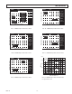
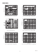
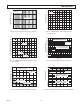
Listing 1. An 80C51 Software Routine for the TMP04
;
; Test of a TMP04 interface to the 8051,
; using timer 0 and timer 1 to measure the duty cycle
;
; This program has three steps:
; 1. Clear the timer registers, then wait for a low-to-
; high transition on input P1.0 (which is connected
; to the output of the TMP04).
; 2. When P1.0 goes high, timer 0 starts. The program
; then loops, testing P1.0.
; 3. When P1.0 goes low, timer 0 stops & timer 1 starts. The
; program loops until P1.0 goes low, when timer 1 stops
; and the TMP04’s T1 and T2 values are stored in Special
; Function registers 8AH through 8DH (TL0 through TH1).
;
;
; Primary controls
$MOD51
$TITLE(TMP04 Interface, Using T0 and T1)
$PAGEWIDTH(80)
$DEBUG
$OBJECT
;
; Variable declarations
;
PORT1 DATA 90H ;SFR register for port 1
;TCON DATA 88H ;timer control
;TMOD DATA 89H ;timer mode
;TH0 DATA 8CH ;timer 0 hi byte
;TH1 DATA 8DH ;timer 1 hi byte
;TL0 DATA 8AH ;timer 0 lo byte
;TL1 DATA 8BH ;timer 1 low byte
;
;
ORG 100H ;arbitrary start
;
READ_TMP04: MOV A,#00 ;clear the
MOV TH0,A ; counters
MOV TH1,A ; first
MOV TL0,A ;
MOV TL1,A ;
WAIT_LO: JB PORT1.0,WAIT_LO ;wait for TMP04 output to go low
MOV A,#11H ;get ready to start timer0
MOV TMOD,A
WAIT_HI: JNB PORT1.0,WAIT_HI ;wait for output to go high
;
;Timer 0 runs while TMP04 output is high
;
SETB TCON.4 ;start timer 0
WAITTIMER0: JB PORT1.0,WAITTIMER0
CLR TCON.4 ;shut off timer 0
;
;Timer 1 runs while TMP04 output is low
;
SETB TCON.6 ;start timer 1
WAITTIMER1: JNB PORT1.0,WAITTIMER1
CLR TCON.6 ;stop timer 1
MOV A,#0H ;get ready to disable timers
MOV TMOD,A
RET
END
Software for the interface is shown in Listing 1. The program
monitors the TMP04 output, and turns the counters on and off
to measure the duty cycle. The time that the output is high is mea-
sured by Timer 0, and the time that the output is low is measured
by Timer 1. When the routine finishes, the results are available
in Special Function Registers (SFRs) 08AH through 08DH.