
Datasheet


TMP03/TMP04
REV. A
–15–
Monitoring Electronic Equipment
The TMP03 are ideal for monitoring the thermal environment
within electronic equipment. For example, the surface-mounted
package will accurately reflect the exact thermal conditions which
affect nearby integrated circuits. The TO-92 package, on the
other hand, can be mounted above the surface of the board, to
measure the temperature of the air flowing over the board.
The TMP03 and TMP04 measure and convert the temperature
at the surface of their own semiconductor chip. When the TMP03
are used to measure the temperature of a nearby heat source,
the thermal impedance between the heat source and the TMP03
must be considered. Often, a thermocouple or other tempera-
ture sensor is used to measure the temperature of the source
D
OUT
TMP04
GND
T1 T2
V
CC
CLR
B
A
Q
Q
5V
5V
0.1F
74HC4538
GND
OUT
1
10
74HC373
V
CC
LE
D1 D2 D3
D4
D5
D6
D7
D8
Q1 Q2 Q3 Q4 Q5 Q6 Q7 Q8
2 5 6 9 12 15 16 19
3 4 7 8 13 14 17 18
20
11
5V
3
1
2
3
1
2
5
4
74HC08
1
74HC4520 #1
V
CC
CLK
Q0 Q1 Q2 Q3 Q0 Q1 Q2 Q3
3 4 5 6 11 12 13 14
9
7
815
16
5V
10
EN
EN
2
CLK GND RESET RESET
10
3
13
8
12
11
74HC373
V
CC
LE
D1 D2 D3
D4
D5
D6
D7
D8
Q1 Q2 Q3 Q4 Q5 Q6 Q7 Q8
2 5 6 9 12 15 16 19
3 4 7 8 13 14 17 18
20
11
5V
74HC373
V
CC
LE
D1 D2 D3
D4
D5
D6
D7
D8
Q1 Q2 Q3 Q4 Q5 Q6 Q7 Q8
2 5 6 9 12 15 16 19
3 4 7 8 13 14 17 18
20
11
5V
74HC373
V
CC
LE
D1 D2 D3
D4
D5
D6
D7
D8
Q1 Q2 Q3 Q4 Q5 Q6 Q7 Q8
2 5 6 9 12 15 16 19
3 4 7 8 13 14 17 18
20
11
5V
74HC4520 #2
V
CC
Q0 Q1 Q2 Q3 Q0 Q1 Q2 Q3
3456 11121314
17
9
15
16
5V
10
EN
EN
2
CLK GND RESET RESET
1MHZ
CLOCK
6
T1 DATA (MICROSECONDS) T2 DATA (MICROSECONDS)
GND
T1 T2
CLR
B
A
Q
Q
5V
5V
10F
GND
V+
5V
20pF
3.9k
9
15 14
16
6
7
5
8
4
1k
20pF
74HC86
10pF
10k
4
5
6
NC
NC
CLK
8
GND
OUT
1
10
GND
OUT
1
10
GND
OUT
1
10
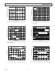
Figure 12. A Hardware Interface for the TMP04
while the TMP03 temperature is monitored by measuring T1
and T2. Once the thermal impedance is determined, the tem-
perature of the heat source can be inferred from the TMP03
output.
One example of using the TMP04 to monitor a high power
dissipation microprocessor or other IC is shown in Figure 13.
The TMP04, in a surface mount package, is mounted directly
beneath the microprocessor’s pin grid array (PGA) package. In
a typical application, the TMP04’s output would be connected
to an ASIC where the pulsewidth would be measured (see the
Hardware Interface section of this data sheet for a typical inter-
face schematic). The TMP04 pulse output provides a significant