
Manual
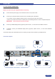
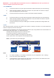
2-2. INPUT #1 DESCRIPTION
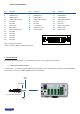
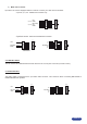
1) CONNECTION :
You can connect to this input one of the following sources :
• A composite video source.
• A S.video source.
• A Component video source.
• A HD-YUV source.
• A RGBS video source.
• An analog (RGBHV, RGsB, RGBS) computer source.
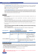
NOTE : You can use the DVI / HD15 adaptor provided with the device to connect analog sources
to the DVI-I (IN) connector.
• A digital computer source.
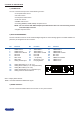
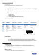
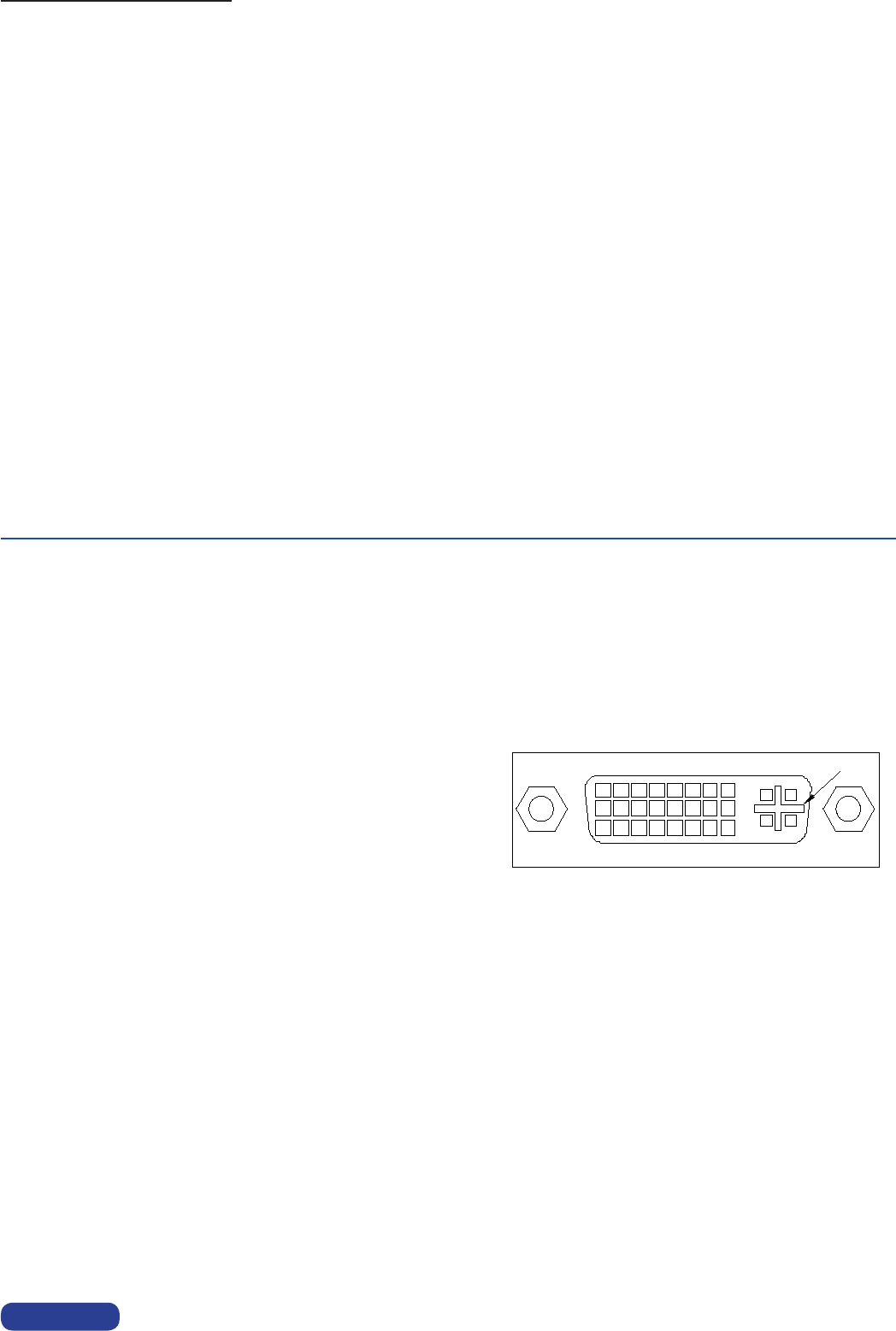
2) DVI-I PIN ASSIGNMENT :
The DVI-I female connector can be used with digital signals as well as analog signals. The table hereafter ex-
plains the pin assignment of this connector.
DDC = Display Data Channel.
TMDS = Transition Minimized Differential Signal.
3) AUDIO SOURCE :
You can connect an AUDIO stereo source to the 3.5 mm jack connector.
8
1
9
16
24
17
C1 C2
C3
C4
C5
PAGE 13
Pin Function Pin Function Pin Function
Pin Function Pin Function Pin Function
1 TMDS Data 2- 9 TMDS Data 1- 17 TMDSData0-
2 TMDS Data 2+ 10 TMDS Data 1+ 18 TMDSData0+
3 TMDS Data 2 Shield 11 TMDS Data 1 Shield 19 TMDSData0Shield
4 Not used. 12 Not used. 20 Not used.
5 Not used. 13 Not used. 21 Not used.
6 DDC Clock 14 + 5V (Power) 22 TMDS Clock Shield
7 DDC Data 15 Ground for (+5V) 23 TMDS Clock+
8 Analog Vertical Sync. 16 Hot plug detect. 24 TMDS Clock-
C1 Analog Red video (or Cr / Pr or C)
C2 Analog Green Video (or Y or composite video)
C3 Analog Bleu Video (or Cb / Pb)
C4 Analog Horizontal Sync (or composite sync)
C5 Analog Common Ground Return