
Manual
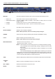
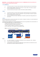
2-3. INPUT #2 to 8 DESCRIPTION
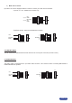
1) CONNECTION :
You can connect to these inputs one of the following sources :
• A composite source.
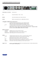
NOTE : Input #7 can accept a composite video source on the BNC connector. Input #8 can accept a
composite on the RCA connector.
• A S.video source.
NOTE : Input #7 can accept a S.video source on the BNC connectors. Input #8 can accept a S.video
source on the 4-pin mini DIN.
• A Component video source.
• A HD-YUV source.
• A RGBS video source.
• An analog (RGBHV, RGsB, RGBS) computer source.
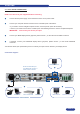
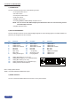
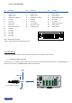
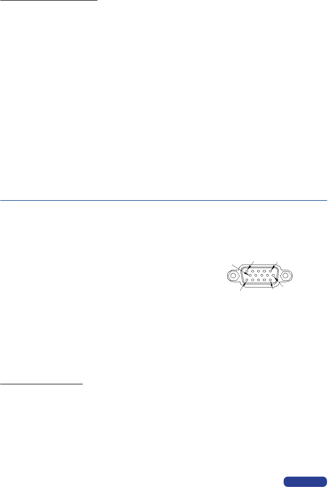
2) HD15 PIN ASSIGNMENT :
5
6
1
15
10
11
HD15 female connector of the device
3) AUDIO SOURCE
• You can connect an unbalanced stereo audio source to the 3.5 jack connector (input #2 & 8).
• You can connect an unbalanced stereo audio source to the MCO connector (input #3 to 6).
• You can connect an unbalanced or balanced stereo audio source to the MCO connector (input #7).
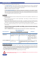
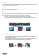
2-4. OUTPUT DESCRIPTION
1) PREVIEW OUTPUT :
Youcanconnecttothisoutputananalogdisplaydevice.ThepreviewoutputformatisXGAat60Hz.
2) MAIN ANALOG OUTPUT :
You can connect to this output an analog display device.
3) MAIN DVI OUTPUT :
You can connect to this output an analog or digital display device.
PAGE 14
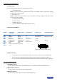
SIGNAL COMPUTER (analog) VIDEO RGB/S YUV & HD-YUV S.VIDEO (Y/C) COMPOSITE VIDEO
SIGNAL COMPUTER VIDEO RGB/S YUV & HD-YUV S.VIDEO (Y/V) COMPOSITE VIDEO
(analog)
PIN 1 RED. RED. Cr / Pr.C (chrominance).
PIN 2 GREEN. GREEN. Y. Y (luminance). VIDEO (NTSC, PAL...)
PIN 3 BLUE. BLUE. Cb / Pb.
PIN 6 RED return. RED return. Cr / Pr return. C return.
PIN 7 GREEN return. GREEN return. Y return. Y return. Return.
PIN 8 BLUE return. BLUE return. Cb / Pb return.
PIN 10 GND. GND.
PIN 13 H sync or C sync (S). C sync (S).
PIN 14 V sync.