User’s Manual MODEL: DSV1600 MODEL: SSV1600 ANALOG WAY® SCAN 1600 / DIGI SCAN 1600 EDITION : 06 / 07
SCAN 1600 / DIGI SCAN 1600 ENGLISH SAFETY INSTRUCTIONS All of the safety and operating instructions should be read before the product is operated and should be retained for further reference. Please follow all of the warnings on this product and its operating instructions. CAUTION: WARNING: To prevent the risk of electric shock and fire, do not expose this device to rain, humidity or intense heat sources (such as heaters or direct sunlight).
SCAN 1600 / DIGI SCAN 1600 INSTRUCTIONS DE SÉCURITÉ Afin de mieux comprendre le fonctionnement de cet appareil nous vous conseillons de bien lire toutes les consignes de sécurité et de fonctionnement de l’appareil avant utilisation. Conserver les instructions de sécurité et de fonctionnement afin de pouvoir les consulter ultérieurement. Respecter toutes les consignes marquées dans la documentation, sur le produit et sur ce document.
SCAN 1600 / DIGI SCAN 1600 SICHERHEITSHINWEISE Um den Betrieb dieses Geräts zu verstehen, raten wir Ihnen vor der Inbetriebnahme alle Sicherheits- und Betriebsanweisungen genau zu lesen. Diese Sicherheits- und Betriebsanweisungen für einen späteren Gebrauch sicher aufbewahren. Alle in den Unterlagen, an dem Gerät und hier angegebenen Sicherheitsanweisungen einhalten.
SCAN 1600 / DIGI SCAN 1600 TABLE OF CONTENTS SAFETY INSTRUCTIONS ...........................................................................................................................................................2 QUICK START GUIDE – DIGI SCAN 1600 ...............................................................................................................................6 QUICK START GUIDE – SCAN 1600................................................................................................
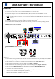
QUICK START GUIDE – DIGI SCAN 1600 ANALOG WAY EDITION : 06/07 CONNECTIONS: c Turn OFF all of your equipment before connecting. d Connect the AC power supply cord to the DIGI SCAN 1600 and to an AC power outlet. e Connect your computer source to the COMPUTER INPUT (HD15) connector or the DVI-D INPUT connector. f As required, connect a control monitor on the MONITOR OUT (HD15) connector. NOTE: Set the RGB Hi-Z/75 Ω button on Hi-Z if you connect a monitor on the MONITOR OUT connector. If not set it on 75 Ω.
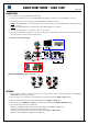
QUICK START GUIDE – SCAN 1600 ANALOG WAY EDITION : 06/07 CONNECTIONS: c Turn OFF all of your equipment before connecting. d Connect your computer source to the COMPUTER INPUT (HD15) connector or the DVI-D INPUT connector. e As required, connect a control monitor on the MONITOR OUT (HD15) connector. NOTE: Set the RGB Hi-Z/75 Ω button on Hi-Z if you connect a monitor on the MONITOR OUT connector. If not set it on 75 Ω. NOTE: The MONITOR OUT is available only if the COMPUTER source is analog.
SCAN 1600 / DIGI SCAN 1600 SCAN 1600 & DIGI SCAN 1600 Chapter 1 : INTRODUCTION 1-1. ACCESSORIES SUPPLIED WITH THE DIGI SCAN 1600 • • • • • 1 DIGI SCAN 1600 1 AC mains cable. 1 VGA cable (HD15 male / HD15 male) 1 CD-ROM (Remote Control Software). 1 User’s Manual. 1-2. ACCESSORIES SUPPLIED WITH THE SCAN 1600 • • • • • • 1 SCAN 1600 1 External power supply 1 AC mains cable. 1 VGA cable (HD15 male / HD15 male) 1 CD-ROM (Remote Control Software). 1 User’s Manual.
SCAN 1600 / DIGI SCAN 1600 Chapter 1 : INTRODUCTION (continued) 1-4. SCAN 1600 GENERAL INFORMATION Scan 1600 by Analog Way is a Scan Converter to convert PC, Mac or Workstation graphic images up to 1600x1200 at60Hz into Video. Ready for the new generation of computer graphic cards, it also offers a standard DVI-D input for digital signal. It is totally Auto-Scan and converts in real time, full screen image, with overscan / underscan and frame freeze functions.
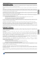
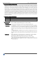
Chapter 1 : INTRODUCTION (continued) SCAN 1600 / DIGI SCAN 1600 1-7. DIGI SCAN 1600 FRONT PANEL DESCRIPTION DIGI SCAN 1600 ANALOG WAY MENU CONTROL R Allows to scroll thru the different menus. ENTER: Validates a selected item. A long push on this button allows to activate the STANDBY mode. A short push on this push button allows to wake up the device. EXIT MENU: Allows to exit from a LCD menu. ADJUSTMENTS POS. SIZE: H: V: ZOOM: FREEZE: Position or Size mode selection.
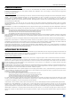
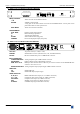
SCAN 1600 / DIGI SCAN 1600 Chapter 1 : INTRODUCTION (continued) 1-9. SCAN 1600 FRONT PANEL DESCRIPTION SCAN 1600 ANALOG WAY MENU CONTROL R Allows to scroll thru the different menus (in Control mode). ENTER: Validates a selected item. A long push on this button allows to activate the STANDBY mode. A short push on this push button allows to wake up the device. EXIT MENU: Allows to exit from a LCD menu. ADJUSTMENTS POS. SIZE: H: V: ZOOM: FREEZE: Position or Size mode selection.
SCAN 1600 / DIGI SCAN 1600 Chapter 2 : STARTING 2-1. DIGI SCAN 1600 CONNECTIONS: c Turn OFF all of your equipment before connecting. d Connect the AC power supply cord to the DIGI SCAN 1600 and to an AC power outlet. e Connect your computer source to the COMPUTER INPUT (HD15) connector or the DVI-D INPUT connector. f As required, connect a control monitor on the MONITOR OUT (HD15) connector. NOTE: Set the RGB Hi-Z/75 Ω button on Hi-Z if you connect a monitor on the MONITOR OUT connector.
SCAN 1600 / DIGI SCAN 1600 Chapter 2 : STARTING (continued) 2-2. SCAN 1600 CONNECTIONS: c Turn OFF all of your equipment before connecting. d Connect your computer source to the COMPUTER INPUT (HD15) connector or the DVI-D INPUT connector. e As required, connect a control monitor on the MONITOR OUT (HD15) connector. NOTE: Set the RGB Hi-Z/75 Ω button on Hi-Z if you connect a monitor on the MONITOR OUT connector. If not set it on 75 Ω.
SCAN 1600 / DIGI SCAN 1600 Chapter 3 : FRONT PANEL DISPLAY MENU DESCRIPTION 3-1. INTRODUCTION The front panel display menu presents 2 modes: the STATUS MODE and the CONTROL MODE. • The STATUS MODE indicates the input and output status of the device. • The CONTROL MODE allows selecting and adjusting the parameters of the device. 3-2. CONTROL BUTTONS The front panel display is controlled by 2 buttons and 1 knob: knob: • In the CONTROL MODE, turn this knob to scroll thru the different menus.
SCAN 1600 / DIGI SCAN 1600 Chapter 3 : FRONT PANEL DISPLAY MENU DESCRIPTION (continued) 3-4. CONTROL MODE The menus of the device are configured as follow: 1 Input 2 Output 1 Input status 2 Input select 3 SOG input 4 H. sync. load 5 Genlock load(1) 6 Genlock H. ph.(1) 7 Genlock Sc. ph.(1) 1 Output status 2 Output std. DVI no Hi-Z Hi-Z 1 NTSC 59.94 Hz 2 PAL 50 Hz 3 NTSC J 59.
Chapter 3 : FRONT PANEL DISPLAY MENU DESCRIPTION (continued) SCAN 1600 / DIGI SCAN 1600 3-5. FUNCTIONS DESCRIPTION 1 [INPUT] + ENTER. 1-1 [Input status] + ENTER. Displays the input status. 1-2 [Input type] + ENTER. Select one of the following input types with + ENTER: • [analog]: Analog computer source connected to the HD15 input connector. • [DVI] : Digital computer source connected to the DVI input connector. 1-3 [SOG input] + ENTER.
SCAN 1600 / DIGI SCAN 1600 Chapter 3 : FRONT PANEL DISPLAY MENU DESCRIPTION (continued) 3-5. FUNCTIONS DESCRIPTION (continued) 3 [IMAGE] + ENTER. 3-1 [Flicker filter] + ENTER. Select one of the 8 levels of the anti-flicker with and validate with ENTER. 3-2 [Black Level] + ENTER. (Available for analog input source only). Adjust the Black level with + ENTER. 3-3 [RGB Levels] + ENTER. (Available for analog input source only). Select an item with + ENTER.
SCAN 1600 / DIGI SCAN 1600 Chapter 4 : UPDATING THE DEVICE The device can be updated thanks a computer (PC) via its RS-232 communication port. c Power OFF the device. d Connect the RS232 connector of the device to the serial port of your computer with a DB9 M/F straight cable. e Open the file: Scan 1600.exe (in Start > Program > ANALOGWAY > SCAN1600 updater). f In the Port menu select the Com port connected to the device. g Click on START on the software.
SCAN 1600 / DIGI SCAN 1600 Chapter 5 : REMOTE CONTROL SOFTWARE Your device is shipped with a Windows compatible Remote Control Software. This software allows you to control and make all adjustments by a simple mouse click. NOTE: The latest Remote Control Software is available on our web site: www.analogway.com 5-1. CONNECTIONS -Connect the serial port of your control device to the RS-232 port (DB9 Female connector) of the device with a straight cable (DB9 Female / DB9 Male).
Chapter 5 : REMOTE CONTROL SOFTWARE (continued) SCAN 1600 / DIGI SCAN 1600 5-4. USING THE SOFTWARE c Click on the Input tab and select the Computer input type. d Click on the Output tab, and then select the needed adjustment (output standard, output rate...).
SCAN 1600 / DIGI SCAN 1600 Chapter 5 : REMOTE CONTROL SOFTWARE (continued) 5-4. USING THE SOFTWARE (continued) e Click on the Image tab and adjust your input. f For the DSV1600 only, click on the Genlock tab and make the genlock adjustments.
SCAN 1600 / DIGI SCAN 1600 Chapter 6 : TECHNICAL SPECIFICATIONS 6-1. COMPUTER INPUTS • ANALOG COMPUTER INPUT Connector: HD15 female. Line frequency: From 29 kHz to 110 kHz. Frame frequency: Up to 130 Hz. Resolution: Up to 1600 x 1200. Signal & Sync. type: RGBHV, RGB/S, RGsB (Sync On Green). Level: R, G, B: 0.7 Vp/p. H & V Sync: TTL. Composite Sync: TTL and 0.3 V. SOG (Sync On Green): 0.3 V. Impedance: R, G, B: 75 Ohm H: Hi-Z or 75 Ohm. V: Hi-Z • DIGITAL COMPUTER INPUT Connector: DVI-I female.
SCAN 1600 / DIGI SCAN 1600 Chapter 6 : TECHNICAL SPECIFICATIONS 6-2. VIDEO OUTPUTS (continued) • COMPOSITE VIDEO Connector: BNC female. Standard: PAL : 15.625 kHz / 50 Hz - 625 lines. NTSC : 15.734 kHz / 60 Hz - 525 lines - 7.5 IRE. NTSC J : 15.734 kHz / 60 Hz - 525 lines - 0 IRE. Level: 1 Vp/p (0.7 V Luma + 0.3 V Sync.). Impedance: 75 Ohm. • SDI (available on the DSV1600 only) Connector: BNC female. Signal: 270 Mbps serial digital output according to SMPTE 259M. Impedance: 75 Ohm. 6-3.
SCAN 1600 / DIGI SCAN 1600 APPENDIX A: PROGRAMMER'S GUIDE ANNEXE A: GUIDE DE PROGRAMMATION A-1: INTRODUCTION A-1: INTRODUCTION If you need to use your own Software Control program from a PC or WORKSTATION with an RS-232 port, the device allows communication through an ASCII code protocol. The device treats any character that it receives on the RS-232 as a possible command but only accepts legal commands. There is no starting/ending code needed in a command string.
SCAN 1600 / DIGI SCAN 1600 APPENDIX A / ANNEXE A A-4: COMMANDS AND RESPONSES TABLE COMMAND RESPONSE COMMANDE RÉPONSE COMMAND DESCRIPTION A-4: TABLE DES COMMANDES ET RÉPONSES TYPE DESCRIPTION DE LA COMMANDE FRONT PANEL COMMANDS / COMMANDES DE LA FACE AVANT z FRZ FREEZE. Rd/Wr a ASP Size mode selection. Rd/Wr h v w s H V W S HP VP HW VS ZHP ZVP ZHW ZVS Horizontal position adjustment. Vertical position adjustment. Horizontal size adjustment. Vertical size adjustment. Zoom horizontal position.
APPENDIX A / ANNEXE A COMMAND RESPONSE COMMANDE RÉPONSE SCAN 1600 / DIGI SCAN 1600 COMMAND DESCRIPTION TYPE DESCRIPTION DE LA COMMANDE STATUS COMMANDS / COMMANDES D’ETAT U UNIT Measures unity in kHz. il ILD This command allows to calculate the input line frequency in kHz id IFD This command allows to calculate the input frame frequency in Hz. ik IST Input sync type detection VALUE /VALEUR MIN MAX Rd Rd 0 0 Rd 0 Rd 0 Input sync detection. Sign of the horizontal input sync.
SCAN 1600 / DIGI SCAN 1600 APPENDIX A / ANNEXE A A-5: TABLE ASCII / HEX / DEC A-5: ASCII / HEX / DEC TABLE ASCII space ! " # $ % & ’ ( ) * + , .
SCAN 1600 / DIGI SCAN 1600 WARRANTY Analog Way warrants the product against any defects in materials and workmanship for a period of three years from the date of purchase (back to the factory). In the event of any malfunction during the warranty period, Analog Way will, at its discretion, repair or replace the defective units, including free materials and labor.