
User guide

10
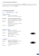
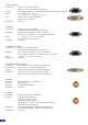
2-2. UNPACKING AND INSPECTION
1 x Smart Edge (STE100)
1 x AC Power cable
2 x DVI-I male to HD15 female and DVI-D female
breakout cable
1 x HD15 to 5 BNC cable
1 x Ethernet cross cable (for device update)
1 x Set of 3 audio 5-pin screw terminals
1 x RCS - Remote Control Software (PC only) *
1 x User Manual (PDF version) *
1 x Quick Start Guide
Optional:
1 x Sync Cable for multiple machine mode (Ref: AW212080)
* Download on our website: www.analogway.com
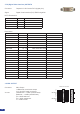
2-3. RACKMOUNT INFORMATION
Tabletop mounting: The STE100 can be used directly on a table, the unit is equipped with 4 handy anti-slip
rubber feet.
Rack mounting: The STE100 is compatible with a 19” enclosure. Please follow the instructions below to install
the device in a 19” rack.
Place the device in your rack. Attach the device to the rack by using 4 screws through the front panel holes
(screws not included).
Rear xing is also recommended, in particular for permanent installations. The STE100 is equipped with drill
holes designed for compatibility with most rackmount braces.
Connect all of the cables of the device and attach them to the rack with the help of tie wraps.
IMPORTANT:
- The openings in the side and rear panels of the device are for cooling. Do not cover these openings to avoid
cutting air circulation.
- Be sure that no weight in excess of 2 kg (4.4 Lbs.) is added onto the STE100.
- The maximum ambient operating temperature should not exceed 40°C (104°F).
- The rack and all mounted equipment in it must be reliably grounded according to national and/or local electrical
standards.
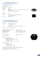
WARNING!
If required, front handles of the device can be dismantled,
but with caution.
The original screws removed must not be reintroduced to
their location without handles in place.
Substantial damages can occur, including risk of electric
shock from the mains voltage.
Only M4x12mm screws can be used.
(They are supplied with the unit)
Dismantling front handles of the device could invalidate warranty on after sales services of your
STE100. It is strongly advised to avoid using front handles as rests for your STE100, they are
designed for manipulation purposes only.
If required, front handles of the device can be dismantled, but with caution.The original screws removed
must not be reintroduced to their location without handles in place. Substancial damages can occur,
including risk of electric shock from the main voltage. Only M4x12mm screws can be used. They are
supplied with the unit.
!