
User guide

SMX System MultiMatrix Switcher • Operation 27
Using the Front Panel
NOTE: This function is available only when the unit is in Lock mode 0.
1. Press and hold the Enter, Preset, View, and Esc buttons simultaneously until the control
buttons and I/O plane buttons 0 and 1 light.
2. Use the control buttons to select the baud rate:
• Enter = 9600 • Preset = 19200 • View = 38400 • Esc = 115200
The selected baud rate button flashes.
3. Use the I/O plane buttons (0 and 1) to select the connection type. The selected
connection type button flashes.
• I/O plane button 0 = RS-232 • I/O plane button 1 = RS-422
4. Press any input or output button to exit configuration mode.
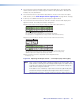
Viewing and Adjusting the Audio Input Level
The audio level of each input can be displayed and adjusted through a range of -18 dB
through +24 dB. It can be adjusted from the front panel, through RS-232 or RS-422, or
through Ethernet (see SIS Configuration and Control on page 33 to make adjustments
using SIS commands).
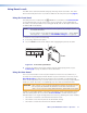
Using the Front Panel
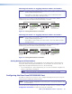
1. Press and release the Esc button to clear all pending changes (flashes green once).
2. Select the audio plane to be viewed and adjusted. The button lights red or amber.
3. Press and hold any I/O button until the audio plane button flashes red (approximately
2 seconds), and then release the button. All I/O buttons extinguish.
4. Press and release a desired input button. It lights green. The input audio level
is displayed by the lit and flashing output buttons (see the Audio Input Level
Adjustment Lighting Table on page 28 for button lighting and dB lighting) and the
color indicates the polarity (+ is green; – is red).
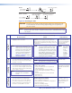
5. Press and release the View (<) button for attenuation (–), and Esc (>) button for gain (+)
to increase or decrease the audio level (see figure 25).
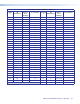
See the Audio Input Level Adjustment Lighting Table on page 28 for a table of
audio level settings.
INPUTS
1
2
3 4
5
6 7 8
9
10
11 12
13 14 15 16
OUTPUTS
1
2
3 4
5
6 7 8
9
10
11 12 13 14 15 16
INPUTS
1
2
3 4
5
6 7 8
9
10
11 12
13 14 15 16
OUTPUTS
1
2
3 4
5
6 7 8
9
10
11 12 13 14 15 16
Step 1 – Press and release Esc.
Flashes green once and clears pending changes.
I/O PLANE SELECT
1
2
3
4
5
6 7 8
9
10
11 12 13 14 15
0
Plane button lights red, indicating an audio (signal) plane.
Step 2 – Press audio I/O plane button to be adjusted (here button 4).
INPUTS
1
2
3
4
5
6 7 8
9
10
11 12
13 14 15 16
OUTPUTS
1
2
3 4
5
6 7 8
9
10
11 12 13 14 15 16
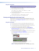
I/O button 1 lights red.
Step 3 – Press and hold any I/O plane button until audio plane button flashes.
Selected audio plane button flashes red and I/O button turns off.
I/O PLANE SELECT
1
2
3
4
5
6 7 8
9
10
11 12 13 14 15
0
INPUTS
1
2
3 4
5
6 7 8
9
10
11 12
13 14 15 16
OUTPUTS
1
2
3 4
5
6 7 8
9
10
11 12 13 14 15 16
I/O button momentarily lights red until audio plane button flashes. I/O button 1 turns off.
Step 4 – Press the button for the input needing the audio level adusted (here 8).
Selected input button lights green, and View button lights red.
The current audio level dB is indicated by the lit and flashing output buttons.
Here buttons 1-4 lit and 5 flashing red indicates an input level of -9 dB.
(See Figure 25 for button lighting and dB levels.)
ENTER
Step 5 – Press and hold View to decrease or Esc to increase audio level.
Selected control button lights red (in this example, Esc was pressed).
C O N T R O L
PRESET
ESCVIEW
N View button lights red and output buttons are red when current
audio level is negative dB, and Esc button lights red and output
buttons are green when it is positive dB.
Selected input button remains lit. Outputs light, flash, or go out as the level changes.
Here the dB is raised to +20 dB. Outputs 1-10 are lit green.
Additional inputs can be adjusted by repeating steps 4 and 5.
Step 6 – Press Enter to leave the input audio level adjustment mode.
All buttons go out.
Figure 25. Adjusting the Input Audio Levels — an Example (Steps 5 and 6)