ANALYTIC SYSTEMS Power Conversion Solutions INSTALLATION & OPERATION MANUAL BCA1050/1550 BATTERY CHARGERS PWS1050/1550 POWER SUPPLIES An ISO9001 Registered Company Battery Chargers • Inverters • Power Supplies • Voltage Converters 101-8128 River Way, Delta B.C. V4G 1K5 Canada T. 604.946.9981 F. 604.946.9983 TF. 800.668.3884 (US/CANADA) www.AnalyticSystems.
Copyright (2005-2020) Analytic Systems Ware (1993) Ltd.
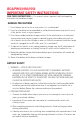
BCA/PWS/1050/1550 IMPORTANT SAFETY INSTRUCTIONS SAVE THESE INSTRUCTIONS — This manual contains important safety and operating instructions for the battery charger. GENERAL PRECAUTIONS 1. Do not expose the unit to rain or snow unless it is a sealed model. 2. U se of an attachment not recommended or sold by the manufacturer may result in a risk of fire, electric shock, or injury to persons. 3.
v. NEVER smoke or allow a spark or flame in the vicinity of a battery. vi. Be extra cautious to reduce risk of dropping a metal tool onto battery. It might spark or short-circuit the battery or other electrical part that may cause a fire or explosion. vii. Remove personal metal items such as rings, bracelets, necklaces, and watches when working with a lead-acid battery. A lead-acid battery can produce a short- circuit current high enough to melt metal, causing a severe burn. viii.
TABLE OF CONTENTS • Front Cover, Product Photo and Title • Product Warning and Advisories • Table of Contents • Introduction • Front Panel Configurations • Battery Charger Operation • Power Supply Operation • Installation • AC Input Connection • DC Output Connection • Battery Temperature Sensors • Equalize Cycle • Product Options • Troubleshooting • Specifications • Warranty ANALYTIC SYSTEMS Power Conversion Solutions Copyright Analytic Systems Ware (2020) Ltd.
Introduction The 1050/1550 family of COTS AC-source battery chargers (BCA) and power supplies (PWS) are designed to supply a DC load or charge a battery at 12, 24, 32, 36, 48 or 72 (Rail) VDC. The 1050 family provides up to 1000 watts of precision power, while the 1550 family can supply up to 1550 watts. These 1050 and 1550 families are identical to their previous models (1005 and 1505, respectively) in form, fit, and function and is a direct drop in replacement for their predecessors.
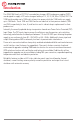
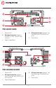
Front Panel Configurations 1 5 2 6 7 3 8 4 9 BCA1050/1550 1. Indicator LEDs 5. Stage Select Switch 2. Battery Temperature Sensor Connection: 2x RJ45 ‘telephone jack’ connector 6. Power Switch 7. AC Input Connection: 3 m / 9.8ft 3xAWG14 power cord with NEMA 5-15 or CEE 7/VII plug 8. Input Fuse 9. Equalize Start button 3. DC Output Connection: 2x Colorcoded Phoenix VDFK6 terminal blocks 4. Output Voltage Adjust 1 5 6 2 3 7 4 8 BCA1050W/1550W 1. Indicator LEDs 4.
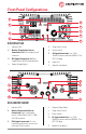
Front Panel Configurations 1 5 2 6 3 7 4 8 BCA1050M/1550M 1. Indicator LEDs 5. Stage Select Switch 2. Battery Temperature Sensor Connection: Amphenol 4-hole Circular MIL-Spec PT02A-8-4S 6. Power Switch 7. AC Input Connection: Amphenol 3-pin Circular MIL-spec GTS02R16-10P connector 8. Equalize Start button 3. 4. DC Output Connection: Amphenol GTC02R22-22S-RDS 4-hole MIL-Spec connector Output Voltage Adjust 1 5 2 6 3 7 4 8 BCA1050MW/1550MW 1. Indicator LEDs 4.
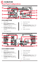
1 4 5 2 3 6 PWS1050/1550 1. Indicator LEDs 2. DC Output Connection: Color-coded Phoenix VDFK6 terminal blocks 3. Output Voltage Adjust 4. AC Input Connection: 3 m / 9.8ft 3xAWG14 power cord with NEMA 5-15 or CEE 7/VII plug 5. Power Switch 6. Input Fuse 1 4 2 5 3 PWS1050W/1550W 1. Indicator LEDs 4. 2. DC Output Connection: 4x color-coded 8AWG flying input leads encased in a watertight Sealcon gland AC Input Connection: 3 m / 9.
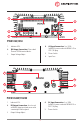
1 4 2 5 3 PWS1050M/1550M 1. Indicator LEDs 4. 2. DC Output Connection: Amphenol GTC02R22-22S-RDS 4-hole MIL-Spec connector AC Input Connection: Amphenol 3-pin Circular MIL-spec GTS02R16-10P connector 5. Power Switch 3. Output Voltage Adjust 1 4 2 5 3 PWS1050MW/1550MW 1. Indicator LEDs 4. 2. DC Output Connection: Amphenol 4-hole Circular MIL-spec GTC02R22-22SRDS connectors AC Input Connection: Amphenol 3-pin Circular MIL-spec GTS02R16-10P connector 5. Power Switch 3.
Battery Charger Operation (BCA) The BCA1050/BCA1550 series battery chargers are designed for simple and intuitive operation. Before operating, make sure this unit is properly installed and connected. See Installation for more information. TO CHARGE A BATTERY 1. Select the type of charging profile using the Stage Select switch on the front panel. See Charging Profiles for more information. 2. Move the Power Switch to ON.
Power Supply Operation (PWS) The PWS1050/PWS1550 series power supplies are designed for simple and intuitve operation. Before operating the unit, it must be properly installed and connected. See Installation for more information. TO POWER A LOAD 1. Move the Power Switch to ON. The alarm buzzer will sound and the LOW VOLTAGE OUTPUT LED will glow red briefly, then the POWER LED will glow green. 2.
Operational Indicators This unit features seven indicator LEDs on its front panel to display the unit’s operating condition. The meanings of these LEDs are detailed below. For more information on the LEDs relating to alarm conditions, see Troubleshooting. BCA ONLY LEDS EQUALIZE [1] THE BATTERY TEMPERATURE SENSOR MUST BE INSTALLED TO USE THIS FUNCTION This LED glows red when the unit is performing an Equalize cycle.
Installation MOUNTING All 1050 and 1550 units weigh approximately 20lbs (9.1 kg) and can be safely mounted on either a horizontal or vertical surface. Mount the unit in a dry and well ventilated location at least 1 inch (2.54 cm) surrounding clearance. The W-series models are designed to meet IP66 rating, and is resistant to water spray from any direction. These units can be mounted in wet locations but are not suitable for submersion. The Y-series models are designed and certified to meet IP67 rating.
AC Input Connection The AC Input connection is intended for connection to the AC power source that is powering the battery charger or power supply. All 1050 and 1550 units feature Power Factor Correction technology on the input and can operate from any AC input voltage from 90-264 VAC. Some units may require wiring to this connection. To determine suitable wiring, the rated input voltage and current values can be found on the unit label located on the XXXX panel.
DC Output Connection The DC Output Connection is intended for connection to the batteries being charged or DC load being powered by the battery charger or power supply, respectively. To ensure normal operation, the total average connected load should not exceed the unit’s output amps rating. Some units may require wiring to this connection. To determine suitable wiring, the rated output voltage and current values can be found on the unit label located on the XXXX panel.
1050/1550 Base BCA and PWS units are equipped with two sets of Phoenix VDFK terminal block connectors to serve as a DC Output Connection. This polarity of this connection can be found on the front panel label and is also as follows: Connector Color Polarity Black Negative Red Output Positive 1050W/1550W W-series and Y-series BCA and PWS units are equipped with two sets color-coded flying 8AWG input leads encased in a watertight Sealcon gland to serve as a DC Output Connection.
Battery Temperature Sensor (BCA Only) This unit is supplied with one battery temperature sensor. The sensor communicates the temperature of the battery to the battery charger and is necessary for the charger’s voltage temperature compensation, battery over temperature shutdown and equalize cycle functions.
Equalize Cycle (BCA Only) If a battery is left discharged for too long, sulfate crystals can form on its internal electrode plates. This interferes with their conductance reducing battery’s capacity and charging speed. Your battery charger can perform an Equalize Cycle to correct this condition.
Output Fuse Replacement This unit features output reverse polarity connection protection. If a load or battery is connected to the output in reverse polarity, the output fuses will blow to protect the power supply or battery charger. The unit is inoperable until the fuses are replaced. See the specifications section for rating and make fuses. When replacing the fuses, ALL the fuses must be replaced as they operate in parallel.
Charging Profiles (BCA Only) This unit has both two-stage and three-stage charging capability. You can choose which type of charging is used during operation by using the Stage Select switch located on the FRONT panel. Below are explanations of the two charging profiles: TWO-STAGE CHARGING 1. The battery is charged at constant current until the battery’s voltage reaches the float voltage. 2. The charging current diminishes as necessary to maintain the battery at that voltage. 3.
Digital Meter Option BCA and PWS units built with the V-Option (Digital Voltmeter Ammeter Display) features a bright and easy-toread This option adds approximately 3.0 in / 5.1 cm to the unit’s chassis length with the handle fully upright (5.9 in / 15.0 cm total height) Portable Option BCA and PWS units built with the P-Option (Portable) feature a foldable carrying handle and rugged rubberized feet designed for easy hand transport and portable operation. This option adds approximately 2.1 in / 5.
Remote Control Accessory IMPORTANT: This remote can only be used on Battery Chargers manufactured by Analytic Systems. The remote control panel and 9-pin D-connector are an optional feature for this product line. The remote control panel allows the unit to be operated remotely and duplicates all the diagnostic LED indicators with audible alarm. A built-in dimmer switch allows you to control the brightness of the remote control LEDs.
Troubleshooting This unit is fitted with LED indicators and an alarm buzzer to display and diagnose any problems in operation. In the event of a malfunction, the unit will sound the buzzer to alert you prior to shutting itself down. You should immediately check which LEDs are glowing to determine the cause of the alarm. LED Indicator Meaning BATT. OVERTEMP The temperature of the battery being charged is too high for safe charging.
Input Specifications ALL 1050 UNITS Volts Actual Maximum Input Amps Input Fuse (Circuit Breaker) Input Ripple and Noise Frequency Power Factor Inrush Current 90-264 VAC in, 45-65 Hz 13.1 A (@ 90 VAC in) 25 A Slow Blow Part # MDA25A <50 mV Peak to Peak 45 - 65 Hz >0.
Output Specifications BCA1050, BCA1050W, BCA1050M, BCA1050MW Volts Nominal (VDC) Charging Amps (A) Float Voltage (VDC) Absorption Voltage (VDC) 12 80 13.5 14.4 24 40 27.2 28.8 32 30 36.3 38.4 36 27 40.8 43.2 48 20 54.4 57.6 72 (rail) 15 72.5 76.8 72 13 81.6 86.
BCA1550, BCA1550W, BCA1550M, BCA1550MW Volts Nominal (VDC) Charging Amps (A) Float Voltage (VDC) Absorption Voltage (VDC) 12 100 13.5 14.4 Absorption to Float Switch (Amps) 15 Output Overvoltage Trip (VDC) Output Overvoltage Type Temperature Compensation Coefficient (mV/°C) Equalize Voltage (VDC) Equalize Maximum Amps (A) Equalize Time Recommended Battery Size (Amp-Hours) 24 60 27.2 28.8 32 36 36.3 38.4 9 6.8 36 40.8 43.2 48 28 54.4 57.6 72 (rail) 20 72.5 76.8 4.5 3 72 81.6 86.4 17.0 ±0.5 34.
Environmental Specifications BCA1050, BCA1550, PWS1050, PWS1550 Operating Temperature Range Storage Temperature Range Humidity Isolation Cooling Audible Noise Typical Service Life Warranty Approvals -25°C to +40°C @ maximum output. Derate Linearly 2.
BCA1050MW, BCA1550MW, PWS1050MW, PWS1050MW, Operating Temperature Range Storage Temperature Range Humidity Isolation Cooling Ingress Protection Audible Noise Emissions Shock and Vibration Typical Service Life Warranty Approvals -40°C to +55°C @ maximum output. Derate Linearly 2.
Mechanical Specifications BCA1050, BCA 1550, PWS1050, PWS1550 Length Width Height Clearance Weight Material & Finish Fasteners Input Connections Output Connections Battery Temperature Sensor Connection (*) 16.8 in / 42.7 cm 8.2 in / 20.8 cm 3.8 in/ 9.7 cm 1.0 in / 2.5 cm all around 20.0 lb / 9.9 kg (approximately) Extruded aluminum chassis and bottom cover, billet machined aluminum end plates, all black anodized 18-8 Stainless steel 3 m / 9.
BCA1050MW, BCA1550MW, PWS1050MW, PWS1550MW Length 16.8 in / 42.7 cm Width 8.2 in / 20.8 cm Height 3.8 in/ 9.7 cm Clearance 1.0 in / 2.5 cm all around Weight 20.0 lb / 9.
This page has been intentionally left blank.
This page has been intentionally left blank.
This page has been intentionally left blank.
Limited Warranty 1. The equipment manufactured by Analytic Systems Ware (1993) Ltd. (the “Warrantor”) is warranted to be free from defects in workmanship and materials under normal use and service. 2. This warranty is in effect for: a. 3 Years from date of purchase by the end user for standard products offered in our catalog. b. 2 Years from date of manufacture for non-standard or OEM products c. 1 Year from date of manufacture for encapsulated products. 3.
DESIGNED AND MANUFACTURED BY 800-668-3884 604-946-9983 Support@analyticsystems.com Battery Chargers • Inverters • Power Supplies • Voltage Converters www.analyticsystems.com 101-8128 River Way Delta, B.C. V4G 1K5 | Canada Register Products Online | www.analyticsystems.