INSTALLATION & OPERATION MANUAL BCDi320 Intelligent DC Battery Charger An ISO9001 Registered Company Battery Chargers • Inverters • Power Supplies • Voltage Converters 8128 River Way, Delta B.C. V4G 1K5 Canada T. 604.946.9981 F. 604.946.9983 TF. 800.668.3884 (US/CANADA) www.analyticsystems.
Copyright (2005-2019) Analytic Systems Ware (1993) Ltd.
DC SOURCE BATTERY CHARGER IMPORTANT SAFETY INSTRUCTIONS SAVE THESE INSTRUCTIONS — This manual contains important safety and operating instructions for the battery charger. BATTERY CHARGER PRECAUTIONS 1. Do not expose the battery charger to rain or snow unless it is a sealed model. 2. U se of an attachment not recommended or sold by the battery charger manufacturer may result in a risk of fire, electric shock, or injury to persons. 3.
iv. If battery acid contacts skin or clothing, wash immediately with soap and water. If acid enters eye, immediately flood eye with running cold water for at least 10 minutes and get medical attention immediately v. NEVER smoke or allow a spark or flame in the vicinity of a battery. vi. Be extra cautious to reduce risk of dropping a metal tool onto battery. It might spark or short-circuit the battery or another electrical part and cause a fire or explosion. vii.
Introduction The BCDi320 series Intelligent DC-source Battery Charger works any standard DC voltage to deliver up to 300 watts of precision charging power to charge your 12, 24, 32, or 48 volt battery systems (The batteries must share a common ground). This unit uses advanced Power Factor Correction circuitry on the input to use the electricity in the most effective and efficient way.
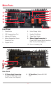
Main Parts 5 1 6 2 7 8 3 9 4 10 Front Panel 1. Power Button 6. End-of-Charge Switch 2. USB Communications Port 7. Equalize Start Button 3. Indicator LED Display 8. Stage Select Switch 4. Battery Temperature Sensor Connection Ports 9. 5. Program Button Battery Output Connection: 2x Phoenix VDFK Terminal Block Connetions (Red: Positive, Black Negative) 10. Chassis Grounding Stud 1 2 Rear Panel 1.
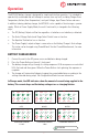
Operation The BCDi320 battery charger is designed for simple and intuitive operation. It is intended to operate fully unattended and will attempt to recover from any fault, including Charger OverTemperature, Battery Over-Temperature, Low Input Voltage, Input Power Failure and more. In addition to being a battery charger, the BCDi320 is also capable of functioning as a power supply.
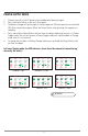
POWER SUPPLY MODE 1. 2. 3. 4. 5. Connect the unit to the DC power source and batteries being charged. Press the Power Button on the unit’s front panel. The battery charger will go through its startup sequence. All 6 microprocessor-controlled LEDs flash red and then green. When the Power Button starts glowing, the sequence is complete. Press and hold the Power Button until you hear two beeps,indicating the unit is in Power Supply mode.
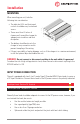
Installation MOUNTING When mounting your unit, take the following into consideration: • The indicator LEDs and front panel controls should be easy to read and access. • There are at least 2 inches of clearance all around the charger for adequate air circulation and heat dissipation. • The battery should be close to the charger to easy connection and to prevent trampling of the wiring.
DC OUTPUT CONNECTION This unit is equipped with a pair of Phoenix VDFK Terminal block connectors to serve as a DC Output connection for connection to battery banks. The connection can support up to two connected battery banks. The polarity for these connections can be found on the unit’s front panel label.
Connection CONNECTION INDICATORS 1. Connect the charger to the batteries as indicated under Installation. I/P 2. Check the POL LED on the front panel. If it is glowing red, the battery is connected in reverse polarity. Correct the connection to the battery (The red terminal should go to Positive and black to Negative). TEMP 25 LO V DEV 75 EQ PS CH POL SVC 50 BAT FLT INPUT POWER PRESENT 3. Once the POL LED is off, connect the charger to the Input power source.
BATTERY TYPE The Battery Type parameters controls the type of charging profile that the unit will use to charge the battery. Different types of batteries have different optimal charging voltages and currents due to their construction and chemical composition. This unit is pre-programmed with four common battery types.
DEFAULT BATTERY TEMPERATURE The Default Battery Temperature parameters controls the charger’s estimated value of the battery temperature. The optimal charging voltage of a battery will decrease as its temperature increases. The charger uses this value to calculate its charging compensation if there are no battery temperature sensors installed and it cannot obtain realtime data.
Front Panel Adjustments Using the two switches between the Program and Select buttons on the front panel, you can select whether a 2-stage or 3-stage charging profile is used to charge the batteries and control the battery charger’s behavior when the charging cycle ends. END-OF-CHARGE SELECT The End-of-Charge (EOC) select switch controls the charger’s behavior after it finishes charging the battery/ batteries.
Charging Profiles This unit has both two-stage and three-stage charging capability. You can choose which charging profile is used during operation by using the Stage Select switch on the front panel. Below are explanations of the two profiles: TWO-STAGE CHARGING • • • • The battery is charged at a constant current until the battery’s voltage reaches the float voltage. Then the charging current diminishes as necessary to maintain the battery at that voltage.
Equalize Cycle If a battery’s cells are left discharged for too long, sulfate crystals can form on the plates interfering with their conductance. This reduces the battery’s capacity and recharging ability. An equalize cycle is a deliberate overcharge of the battery at high voltage (110% of float voltage) and low current (10% of standard output) to force undercharged cells to match charge of the good cells in the battery.
Battery Temperature Sensor This unit is supplied with one battery temperature sensor. This sensor communicates the temperature of the battery to the charger and is required to access the charger’s voltage temperature compensation, batttery over temperature alarm and equalize cycle functions.
Maintenance This charger requires no maintenance other than the occasional wipe down to remove dust that could reduce its ability to dissipate heat. Carefully blow air through the cooling vent to remove any dust buildup inside the unit. Dry Contact Relay The charger can be fitted with a 1 amp dry contact relay to indicate charger status to a monitoring system.
Troubleshooting The BCDi320 is designed to provide years of reliable service and to auto-recover in the event of an operational failure. In the event of malfunction, the unit is fitted with eight LED indicators and an audible alarm to help diagnose the cause of the issue. Below is a list of potential issues, and how to repair them.
FAULT INDICATORS TEMP 25 I/P LO V DEV SVC 50 75 EQ PS CH POL BLINKING BAT FLT CHARGER FAILED TEMP 25 I/P LO V DEV 75 EQ PS CH POL SVC 50 BAT FLT BATTERY FAILED I/P TEMP 25 LO V 50 DEV 75 EQ PS CH POL SVC BAT FLT Charger Failure Indication The microprocessor has detected a condition that prevents the charger from operating. Try disconnecting the Input power and re-connecting it.
Glossary We use a number of abbreviations on the labels to save space. Here are the full words corresponding to each abbreviation along with common battery charger terms and their definitions: ABBREVIATIONS POL – Polarity. Refers to the correct connection of the Positive and Negative terminals of the battery to the charger. DEV – Device. Refers to the charger. Used together with the Fault LED to indicate a problem with the Device. BAT – Battery. Refers to the battery.
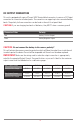
Specifications Input Volts (VDC) 100-350 VDC Current (max) * 4 Amps w. Inrush Protection Input Fuse 6.3A 400 VDC Power Factor > 0.99 at Full Load Efficiency > 90% at Full Load *Maximum Input Current Specified at 85 VAC Output Nominal Voltage 12 VDC 24 VDC 28 VDC 32 VDC 36 VDC 48 VDC Voltage Range (VDC)** 12.0-15.5 24.0-31.0 28.0-36.2 32.0-41.3 36.0-46.5 48.0-62.0 Output Current 20 A 10 A 8A 7.5 A 7 A 5A Recommended Battery (AmpHours) 100 50 45 40 33 25 Standard.
Limited Warranty 1. The equipment manufactured by Analytic Systems Ware (1993) Ltd. (the “Warrantor”) is warranted to be free from defects in workmanship and materials under normal use and service. 2. This warranty is in effect for: a. 3 Years from date of purchase by the end user for standard products offered in our catalog. b. 2 Years from date of manufacture for non-standard or OEM products c. 1 Year from date of manufacture for encapsulated products. 3.
DESIGNED AND MANUFACTURED BY 800-668-3884 604-946-9983 sales@analyticsystems.com Battery Chargers • Inverters • Power Supplies • Voltage Converters www.AnalyticSystems.com 8128 River Way Delta, BC V4G 1K5 | Canada Register Products Online | www.analyticsystems.