Copyright © 6/11 All Rights Reserved Analytical Industries Inc. dba Advanced Instruments Inc., 2855 Metropolitan, Pomona, CA 91767 USA. Tel: 909-392-6900, Fax: 909-392-3665 Email: sales-industrial@aii1.com, Web: www.aii1.com This manual may not be reproduced in whole or in part without the prior written consent of Analytical Industries Inc.
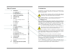
Table of Contents 1 1 Introduction Introduction 1 1.1 1.2 1.3 1.4 1 2 3 4 Indications for Use Intended Use Device Description Declaration of Conformity 2 Quality Control Certification 5 3 Safety Warnings 6 4 Start-up 8 4.1 4.2 4.3 4.4 4.5 5 6 Contents of Shipping Container Controls Start-Up Test Calibration Mounting 8 8 8 9 11 Operation 12 5.1 5.2 5.3 5.4 12 13 15 15 Principle of Operation Application Considerations Calibration Sampling Maintenance 17 6.1 6.2 6.3 6.4 6.
The device is intended to be re-usable. Should the device or accessories come in contact with patient bodily fluids, either dispose of the device or clean with a soft cloth dampened with 70% isopropyl alcohol solution in water and allow the components to air-dry before re-use .
1.4 Declaration of Conformity Manufacturer: Authorized EC Representative: Product: 2 Quality Control Certification Analytical Industries Inc. 2855 Metropolitan Place, Pomona, California 91767 USA Tel: 909-392-6900, Fax: 909-392-3665 e-mail: sales-medical@aii1.com, www.aii1.com RGV Lda.
3 Safety Warnings ALWAYS follow the statements below as they are essential to reducing the risk of use error due to ergonomic features of the device or the environment in which the device is intended to be used. NEVER operate the device in any manner described below doing so may compromise the clinical condition or the safety of patients, users or other persons. If the reading is unstable or a malfunction is suspected. After the battery symbol appears in the LCD display.
4 Start-Up 4.1 Contents of Shipping Container: The contents include: AII-2000 Palm O2 Oxygen Analyzer FITN-1112-1 Flow Diverter P-1088 Instruction for Use Note: See section 6.5 for remote sensor option and Section 8.1 for optional accessories. The device is shipped with the batteries and oxygen sensor installed at the factory and is ready for calibration and use. Any optional equipment is secured in a plastic bags and stored next to the analyzer in the shipping container.
Procedure Calibrate: (a) with a known source of dry 100% or 21% oxygen before using each day or after 8 hours of continuous use; (b) when the temperature or pressure of the operating environment changes; (c) if the oxygen sensor has been disconnected and reconnected; (d) after the battery or oxygen sensor has been replaced. 1. 2. 3. 4. 5. 6. 7. Expose the sensor to the calibration gas (refer to preceding section) for approximately 30 seconds to allow the sensor to stabilize.
5 Operation 5.2 Application Considerations 5.1 Principle of Operation The AII-2000 Palm O2 Oxygen Analyzer utilizes an electrochemical galvanic fuel cell type oxygen sensor of the type that is extensively used to measure oxygen concentrations from 0% to 100% in gas streams.
The temperature dependent current signal output is compensated by using a resistor-thermistor network. With a proper resistor-thermistor network, the signal can be compensated to within +5% of the oxygen reading over the 545°C temperature range. This is the worse case situation when going from one extreme of the operating temperature range to the other.
5.4.1 Flowing Gas Streams (Breathing Circuits, Concentrators) 1. Place the sensing area of the sensor into the gas stream to be analyzed upstream of any humidification equipment. 2. Assure that the flow rate of the gas stream does not exceed ten (10) liters per minute. Exceeding ten (10) liters per minute generates backpressure. 3. Check the gas stream and particularly the mechanical connection for leaks that dilute the gas stream with ambient air. 4.
Procedure: 1. Open the enclosure: Remove the four (4) Phillips screws from the rear of the enclosure, FIG 1. 2. Separate the enclosure and an place it on a flat surface, FIG 2. 3. Remove the battery: Grasp the middle of a battery and gently pull straight up. 4. Locate the positive (+) and negative (-) terminals on the battery. 5. Assure the battery contacts are clean. 6. Align the battery’s positive (+) terminal with the corresponding (+) battery symbol printed on the PCB Assembly. 7.
6.5 Oxygen Sensor Replacement - Optional Remote Sensor The design of the electronics is intended for only the Analytical Industries Inc. AII-11-75-PO2 or AII-11-75-PO2R Oxygen Sensors. Use of a different oxygen sensor may result in an erroneous oxygen reading. NEVER - Open the oxygen sensor or probe the sensing surface, refer to Section 10 in the event the sensor should leak and someone comes in contact with the electrolyte from inside the sensor.
8.1 Spare Parts & Optional Accessories 8 Specifications Spare Parts: Accuracy: < 2% of FS range under constant conditions AII-11-75-PO2 Oxygen Sensor Analysis: 0-100% oxygen BATT-1008 Battery (2x) 1.5V AA Alkaline Alarms: Analyzer none P-1087 Instructions for Use Calibration: Certified dry 100% oxygen or air after 8 hrs of use A-1162 PCB Assy Main Compensation: Temperature Connections: 1x16mm thread or o-ring diverter Controls: Soft touch keypad for ON/OFF and CAL Dimensions: 2.
9 Warranty 10 Material Safety Data Sheet (MSDS) Coverage Under normal operating conditions, the analyzer and sensors are warranted to be free of defects in materials and workmanship for the period specified in the current published specifications.