ISO 9001:2008, Certificate #485 AII-3000 AHC AII-3000 A AII-3000 MHC AII-3000 M Copyright © 10/10 All Rights Reserved Analytical Industries Inc., 2855 Metropolitan, Pomona, CA 91767 USA. Tel: 909-392-6900, Fax: 909-392-3665 e-mail: sales-medical@aii1.com, web: www.aii1.com This manual may not be reproduced in whole or in part without the prior written consent of Analytical Industries Inc.
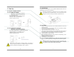
Table of Contents 1 1 Introduction Introduction 1 1.1 Indications for Use 1.2 Intended Use 1.3 Device Description 1 2 2 2 Quality Control Certification 3 3 Safety Warnings 4 4 Start-up 4.1 4.2 4.3 4.4 4.5 4.6 4.7 4.8 5 6 This symbol means CAUTION – Failure to read and comply with the Instructions for Use could damage the device and possibly jeopardize the well being of the user. Note: Advanced Instruments Inc.
In order to obtain optimum performance, the operation of the device must be performed in accordance with these Instructions for Use. Maintenance should be performed only by trained personnel authorized by the manufacturer. 1.
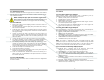
3 Safety Warnings ALWAYS follow the statements below as they are essential to reducing the risk of use error due to ergonomic features of the device or the environment in which the device is intended to be used. NEVER operate the device in any manner described below doing so may compromise the clinical condition or the safety of patients, users or other persons. If the reading is unstable or a malfunction is suspected. After the battery symbol appears in the LCD display.
4.2 Install Batteries All devices are powered by two 1.5V AA alkaline batteries which must be installed before the device can be operated. 4 Start-Up 4.1 Contents of Shipping Container: 4.1.1 AII-3000 A, AII-3000 M: ENCL-1061 V-mount retainer (attached) ENCL-1066 Tripod wire stand (attached) AII-11-60 Oxygen Sensor BATT-1008 Battery, AA 1.5V Alkaline (Qty 2) CABL-1006 Cable, Coiled Phone Jack P-1087 Instructions for Use The battery compartment is located at the rear of all devices.
4.3 Install Oxygen Sensor The device cannot function until the oxygen sensor is installed. Once installed, allow the sensor to stabilize for 15-20 minutes in ambient air before attempting to calibrate the device. NEVER - Attempt to open, repair or service the oxygen sensor. Refer to Section 3 for hints and warnings concerning the handling and environmental considerations of the oxygen sensor and the device. 4.3.1 AII-3000 A/M: 1. Remove the contents from the shipping container as shown in section 4.
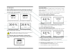
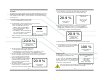
4.5 Start-Up Test Press the ON/OFF key on the front panel to apply power to the device and initiate a complete diagnostic test of all system functions: the electronics, feeds voltage and tests the alarm circuit (monitor only below right) internally, confirms the battery voltage is adequate to power the circuit, and, the sensor’s signal output is within specifications.
4.6 Alarms AII-3000 M/MHC Oxygen Analyzers The monitor is equipped with user selectable HI and LO alarm set points which are displayed at the bottom of the LCD. The default alarm set points are 15% LO and 50% HI. The LO alarm set point can be set between 15% and 99% and the HI alarm set point can be set between 16% and 100%. Alarm set points may be adjusted in 1% increments by pressing and holding the UP/ DOWN ARROW keys, see below.
Procedure AII-3000 Series Oxygen Analyzers employ the identical calibration routine and displays but they differ slightly in the way they arrive at the display that initiates calibration routine. Refer to Set-Up illustration and references above for gas connections. 1. AII-3000 A/AHC - Press the 21% key under the word CALIBRATION on the front panel. 1a. AII-3000 M/MHC - Requires navigating its menu to reach the display that initiates the calibration routine. a.
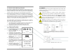
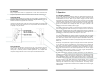
4.8 Mounting Every analyzer and monitor is equipped with a male dove tail bracket and triangular shaped thick metal wire stand secured to the rear of the enclosure. Tripod Wire Stand Secured between bumper feet on either side of the battery compartment is a triangular shaped thick metal wire stand that is hinged under the dove tail bracket secured at the opposite end of enclosure.
5.2 Application Considerations Effect of Temperature All membrane clad electrochemical sensors are temperature dependent due to the expansion and contraction of the Teflon sensing membrane. As result more or less of the sample gas including oxygen to be reacted diffuses into the sensor. The oxygen sensor’s electrical current signal output varies linearly with oxygen concentration. The signal also varies with changes in ambient temperature. The temperature coefficient is typically 2.
5.4.1 Flowing Gas Streams 1. Place the sensing area of the sensor into the gas stream to be analyzed upstream of any humidification equipment. 2. Assure that the flow rate of the gas stream does not exceed ten (10) liters per minute. Exceeding ten (10) liters per minute generates backpressure. 3. Check the gas stream and particularly the mechanical connection for leaks that dilute the gas stream with ambient air. 4.
Initially this procedure can be somewhat difficult. Care should be taken not to damage the case when removing the battery compartment cover. 6.3.2 Procedure AII-3000 AHC and AII-3000 MHC - Integral Sensor 1. Tools required: small bladed screwdriver. 2. Place the device face down on a flat surface. Turn the device over so the shortest raised line on the battery compartment cover is pointing away from you. 3. Remove the two (2) screws from the upper corners of the rear of the device. 4.
12. Once the adapter and old sensor have been removed from the case, hold the label of the sensor, again grasp the square edges of the adaptor and pull – to separate the old sensor from the adaptor. 13. Remove the new oxygen sensor from the plastic shipping container. 14. Install the new oxygen sensor by reversing steps 12 through 3.
Symptom Corrective Action Reading displayed by LCD does not change when calibration control is adjusted Replace sensor Reading displayed by LCD is very low Check sensor connection Check cable connection Replace sensor Alarms vated continuously acti- None – Normal operation, confirm set points Abnormal Adjust alarm set points Remove moisture covering sensor Check sensor connection Check cable connection Check integrity of gas delivery system Check sensor’s front o-ring seal Verify calibration gas in
Expected Sensor Life Considers the full range of the sensor’s signal, example 7-13 mV. Oxygen sensors are configured to meet the published, see preceding page, specification which distributes the overall sensor life as follows: - 60 months Expected Service Life (915,420 oxygen % hours) - 6 months Recommended Storage Life period (91,542 % oxygen hours) - 2 months margin of error Therefore, the Recommended Storage life period should not be considered a perishable shelf life.
9 Warranty 10 Material Safety Data Sheet (MSDS) Coverage Under normal operating conditions, the analyzer and sensors are warranted to be free of defects in materials and workmanship for the period specified in the current published specifications.