
User guide

20
21
5.4.1 Flowing Gas Streams
1. Place the sensing area of the sensor into the gas stream to be analyzed
upstream of any humidification equipment.
2. Assure that the flow rate of the gas stream does not exceed ten (10) liters
per minute. Exceeding ten (10) liters per minute generates backpressure.
3. Check the gas stream and particularly the mechanical connection for leaks
that dilute the gas stream with ambient air.
4. Assure there are no restrictions in the circuit downstream of the sensor
that could generate backpressure on the sensor.
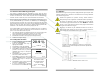
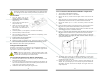
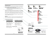
5. Use the optional flow diverter along with the op-
tional tee adapter and position the sensor vertically
for optimum results, as shown right. The flow di-
verter avoids stagnation and facilitates the move-
ment of gas to and from the sensing area of the
sensor thereby producing a more accurate meas-
urement of the gas stream to be measured.
6. Install the tee-adapter in the breathing circuit.
7. Screw the flow diverter to the sensor.
8. Ensure the o-ring is lightly lubricated for ease of
entry and a tight seal between the flow diverter and
tee adapter.
9. Insert the assembled flow diverter/sensor into the tee allowing air or
100% oxygen (dry, non-humidified) to flow past the sensor at a rate of 5-
8 liters per minute.
10. Once the sensing area of the sensor is exposed to the gas stream allow
approximately sixty (60) seconds for the reading to stabilize and observe
the reading displayed by the LCD.
11. Refer to Section 8.1 for a variety of accessories that provide a several
methods of sampling flowing gas streams.
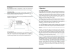
5.4.2 Static Atmospheres
Remove the flow diverter, not needed. Failure to remove the flow diverter will
dramatically slow the response time of the sensor.
Expose the sensing area of the sensor to the atmosphere allowing approxi-
mately sixty (60) seconds for the reading to stabilize and observe the
reading displayed by the LCD.
If placing the entire sensor inside the controlled atmosphere review
Section 5.2 Application Consideration, Effect of Temperature.
5.4.3 AII-3000 AHC and MHC (Integral Oxygen Sensor)
AII-3000 AHC and MHC with their integral oxygen sensor requires connecting
the ¼” tubing supplied (section 4.2.1 above) with the device to a ¼” hose
barb attached to a pressure regulator controlling a source of gas flowing at less
than 10 liters per minute.
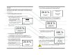
5.5 Alarms (AII-3000 M/MHC):
The monitor is equipped with user selectable HI and LO alarm set points which
are displayed at the bottom of the LCD. Section 4.6 describes the operation
and procedure for setting the alarms in detail.
6 Maintenance
Review Section 3 Safety Warnings and Section 7 Troubleshooting for
guidelines on servicing the devices.
6.1 Serviceability
Do not open the main compartment of the analyzer, as it contains no service-
able parts inside. Never attempt to repair the analyzer or sensor by yourself as
you may damage the analyzer which could void the warranty.
6.1.2 Cleaning / Reuse Instructions
Clean the device, oxygen sensor and accessories with a soft cloth dampened
with either water or mild isopropyl alcohol solution (70% isopropyl alcohol
solution in water), if necessary, before re-use. Allow the components to air-dry
after cleaning.
Note: The Home Care Kit is not intended for patient use, it is intended solely
for confirming the O
2
concentration in Oxygen Concentrators. Accordingly, no
cleaning instructions apply.
6.2 Battery Replacement
The analyzers and monitor are powered by two AA alkaline batteries with an
approximate life of 1,200 hours. A low battery indicator circuit monitors the
battery supply voltage and sends a signal directly to the LCD when the battery
voltage reaches a preset level that activates the battery symbol in the LCD.
The batteries are housed in a separate compartment located at the rear of the
device and are accessible by sliding the removable cover.