
User guide

22
23
Initially this procedure can be somewhat difficult. Care should be taken
not to damage the case when removing the battery compartment cover.
6.2.1 Procedure:
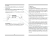
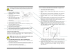
1. Turn the device over so the
shortest raised line on the battery
compartment cover is pointing
away from you.
2. Lift the tripod wire stand up and
away from the case.
3. Grasp the case with both hands
and using your thumbs press
down firmly on the raised lines and push the battery compartment cover
away from you.
4. Locate the positive (+) and negative (-) terminals on the battery.
5. Assure the battery contacts are clean.
6. Align one battery’s positive (+) terminal with the corresponding (+) bat-
tery symbol molded into the case.
7. Insert the battery into the compartment.
8. Repeat with the remaining battery.
9. Replace the battery compartment cover, make sure it snaps into position
and is secured flush against the case. Replace the wire stand as required.
10. Calibrate the device after replacing the batteries.
6.3 Oxygen Sensor Replacement
The design of the electronics is intended for only the Analytical Industries Inc.
AII-11-60 or AII-11-60-HC Oxygen Sensors. Use of a different oxygen sensor
may result in an erroneous oxygen reading.
NEVER - Open the oxygen sensor or probe the sensing surface, refer
to Section 10 in the event the sensor should leak and someone comes
in contact with the electrolyte from inside the sensor.
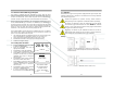
6.3.1 Procedure AII-3000 A and AII-3000 M - External Sensor
1. Disconnect the cable from the old sensor just as you disconnect a tele-
phone jack from a wall plug.
2. To connect the new sensor simply find and register the male plug at the
end of the coiled cable and insert it into the mating female jack at the rear
of the sensor until it mates or snaps into place.
3. Calibrate the device after replacing the oxygen sensor.
6.3.2 Procedure AII-3000 AHC and AII-3000 MHC - Integral Sensor
1. Tools required: small bladed screwdriver.
2. Place the device face down on a flat surface.
3. Remove the two (2) screws from the upper corners of the rear of the
device.
4. Move the tripod up, remove the battery compartment cover (see Battery
Replacement) and remove the two (2) screws located on either side.
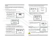
5. Pull the rear section up ¼”-½”, turn it over and lay it next to the other
section.
6. Locate the white connector at the end of the four (4) wires running from
the sensor (the cylinder with the white label) to the top of the PCB.
7. With your left for finger and thumb, grasp the sides of the back end of the
white connector where it is soldered to the PCB.
8. With your right fore finger and thumb, grasp the sides of the section of
the white connector where the four (4) wires from the sensor terminate.
9. Separate the connector - hold the white connector section your left hand
while gently pulling and wiggling the white connector section with your
right hand until it unlocks.
10. The oxygen sensor inserts into an adaptor (identified by a round recess
with a cylindrical hose adapter in the center) that slides into grooves
molded into the side of the case.
11. Hold the rear section of the case down, grasp the square edges of the
adaptor, lift up (lift straight up so as not to strip the grooves molded into
the adaptor and case) and remove the adaptor and oxygen sensor as a
single component.