
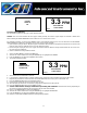
Owner's manual


27
Caution: DO NOT open the oxygen sensor. The sensor contains a corrosive liquid electrolyte
that could be harmful if touched or ingested, refer to the Material Safety Data Sheet contained in
the Owner’s Manual.
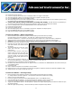
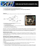
Procedure:
1. Remove the four (4) screws securing the analyzer’s front panel.
2. Caution: Do not discard the gaskets from the enclosure.
3. Using the 5/16 wrench supplied loosen but do not remove the clamp bolt located in the
center of the housing with the elbows attached.
4. Rotate the upper section of the sensor housing 90º to disengage from the clamp.
5. Remove the upper section by pulling it straight up and place it on a smooth surface.
6. Remove the old oxygen sensor and dispose of it as you would a battery.
7. Place the SAMPLE/BYPASS valve in the SAMPLE position, connect zero gas or low oxygen
content sample gas line to purge the sensor of oxygen and begin the flow at 2 SCFH.
8. Remove the new oxygen sensor from the shipping bag.
9. Remove the red label and the gold ribbon (shorting device) from the PCB at the rear of the sensor.
10. Caution: Minimize the time the sensor is exposed to ambient air.
11. Once the reading stabilizes – see above.
12. Span Calibrate the analyzer in 20.9% ambient air.
13. Place the new sensor in the bottom section of the sensor housing with the PCB facing up.
14. Place the upper section of the sensor housing over the sensor.
15. Gently push the upper section downward and rotate 90º to engage the clamp.
16. Finger tighten the clamp bolt and one full turn with the 5/16 wrench to compressed the o-ring seal.
17. With a zero gas containing less than 1 ppm oxygen concentration flowing (see #7 above), expect the analyzer reading to
recover to the 0-100 ppm range in 15 minutes and the 0-10 ppm range within 60 minutes.
18. Begin sampling once the analyzer has reached the value of the purge gas.
19. Note: If a sample gas containing a lower oxygen concentration is subsequently introduced into the analyzer expect the
analyzer reading to continue to decrease gradually.
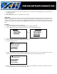
Battery Replacement
Charging the battery requires a common 9VDC adapter (positive pole located inside the female connector) supplied with the
analyzer and a convenience outlet. The analyzer’s charging circuit accepts 9VDC from any standard AC 110V or 220V adapter.
The electronic design enables the analyzer to remain fully operable during the 8-10 hour charging cycle.
Procedure:
1. Unless the analyzer is to be operated while charging, turn the analyzer OFF when charging the battery for the shortest
charging cycle.
2. Connect the appropriate 9VDC adapter supplied with the analyzer to an 110V or 220V outlet.
3. Insert the male phone plug from the 9VDC adapter into the integral female CHARGE jack located on the bottom of the
enclosure.
4. Caution: The analyzer is designed to operate in the charging mode, however, operating the analyzer in hazardous or
explosive atmospheres while charging the battery IS NOT recommended despite the intrinsically safe design.
Service: A single charge is sufficient to operate the GPR-1200 analyzer continuously for a period of 60 days, 1 day when
operating the optional integral sampling pumps continuously.
Warning indicators:
An LED indicator located on the front panel will light continuously during the CHARGE cycle.
A second LED indicator located on the front panel provides a blinking 72 hour warning LOW BATT of the need to recharge the
battery. Caution: Operating the analyzer beyond this 72 hour warning may permanently damage the battery.