Advanced Instruments Inc. GPR-1600 MS ppm Oxygen Analyzer Owner’s Manual 2855 Metropolitan Place, Pomona, California 91767 USA ♦ Tel: 909-392-6900, Fax: 909-392-3665, e-mail: info@aii1.
Advanced Instruments Inc. Table of Contents Introduction 1 Quality Control Certification 2 Safety & Installation 3 Features & Specifications 4 Operation 5 Maintenance 6 Spare Parts 7 Troubleshooting 8 Warranty 9 Material Safety Data Sheets 10 Correlating reading - LCD display to 4-20mA output Appendix B 1 Introduction Your new oxygen analyzer is a precision piece of equipment designed to give you years of use in variety of industrial oxygen applications.
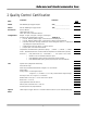
Advanced Instruments Inc. 2 Quality Control Certification Date: Customer: Order No.: Model: GPR-1600MS ppm Oxygen Analyzer S/N _____________________ Sensor: GPR-12-2000MS ppm Oxygen Sensor S/N _____________________ Accessories: Owner’s Manual CABL-1008 Power Cord TOOL-1001 5/16” Combination Wrench Configuration: Ranges: 0-1 ppm, 0-10 ppm, 0-100 ppm, 0-1000 ppm A-1146-20 PCB Assembly Main / Display Software V.
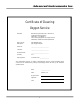
Advanced Instruments Inc. Certificate of Cleaning Oxygen Service Standard: Manufacturing Procedure No. P-1057 Rev-1, Compressed Gas Association, Publication: G-4.1 Edition 4, Title: Cleaning Equipment for Oxygen Service, Published 1/1/1996 and related publications Mfg. Item No.: GPR-1600MS Series Description: ppm Oxygen Analyzer Serial No.
Advanced Instruments Inc. 3 Safety Guidelines Safety This section summarizes the basic precautions applicable to all analyzers. Additional precautions specific to individual analyzer are contained in the following sections of this manual. To operate the analyzer safely and obtain maximum performance follow the basic guidelines outlined in this Owner’s Manual. Caution: This symbol is used throughout the Owner’s Manual to Caution and alert the user to recommended safety and/or operating guidelines.
Advanced Instruments Inc. Installation Gas Sample Stream: Ensure the gas stream composition of the application is consistent with the specifications and review the application conditions before initiating the installation. Consult the factory to ensure the sample is suitable for analysis.
Advanced Instruments Inc.
Advanced Instruments Inc.
Advanced Instruments Inc. 5 Operation Principle of Operation The GPR-1600MS ppm Oxygen Analyzers incorporates a proprietary Pico-Ion oxygen sensor. It is configured for panel mounting and requires a 7.5x10.8” (T configuration) cutout with 4 holes for the analyzer’s front panel. Optional configurations include a panel mount (TO configuration) 7.75x7.75” with cutout; 19” bezel for rack mounting either the T or TO; 12x12x8” wall mount enclosure; 18.
Advanced Instruments Inc. Oxygen, the fuel for this electrochemical transducer, reacts chemically at the sensing electrode to produce an electrical current output proportional to the oxygen concentration in the gas phase. The sensor’s signal output is linear over all four ranges and remains virtually constant over its useful life. The sensor requires no maintenance or electrolyte addition and is easily and safely replaced at the end of its useful life.
Advanced Instruments Inc. Calibration & Accuracy Overview Single Point Calibration: As previously described the galvanic oxygen sensor generates an electrical current proportional to the oxygen concentration in the sample gas. In the absence of oxygen the sensor exhibits an absolute zero, e.g. the sensor does not generate a current output in the absence of oxygen. Given these linearity and absolute zero properties, single point calibration is possible.
Advanced Instruments Inc. Zero Calibration In theory, the galvanic fuel cell type oxygen has an absolute zero meaning it produces no signal output when exposed to an oxygen free sample gas.
Advanced Instruments Inc. * Refer to analyzer specifications for comparable data on the Pico-Ion UHP and MS oxygen sensors. Recommendations General: ¾ The interval between SPAN CALIBRATION should not exceed three (3) months. ¾ Always calibrate at the same temperature and pressure of the sample gas stream. ¾ If a ZERO CALIBRATION adjustment is made during initial installation, it is normally not required again until the sample system connections are modified or a new oxygen sensor is installed.
Advanced Instruments Inc. 3. Note: The proximity of the analyzer to the sample point and use of optional sample conditioning components have an impact on sample lag time.
Advanced Instruments Inc.
Advanced Instruments Inc.
Advanced Instruments Inc. Gas Connections The GPR-1600MS with its standard flow through configuration is designed for positive pressure samples and requires connections for incoming sample and outgoing vent lines, see illustrations above. The user is responsible for calibration gases and the required components, see below. Flow rates of 1-3 SCFH cause no appreciable change in the oxygen reading.
Advanced Instruments Inc. Electrical Connections The appropriate AC power requirement must specified be specified at order placement if the analyzer is to be equipped with the temperature control heater system. Incoming power for the 100-250V AC powered analyzers is supplied through a universal power entry module. A standard computer type power cord (P/N A-1008) is required for the universal power entry module.
Advanced Instruments Inc. Procedure: 1. As illustrated above the sensor, power and alarm relays and signal output connections are hard wired to screw type terminal blocks located at the rear of the analyzer. 2. Use a small bladed screwdriver to loosen the appropriate terminal screws as illustrated above. 3. Strip the wires of the cable no more than 3/16 inch. 4.
Advanced Instruments Inc. Alarms Alarm 1 and Alarm 2 represent two threshold type alarms that can be configured in the field from the analyzer’s menu driven LCD display as follows: ¾ ¾ ¾ ¾ Establish independent set points Either Hi or Lo Either On or Off (enabled or disabled) Both temporarily defeated using a user entered ‘timeout’ period (normally minutes) The alarm set point represents a value.
Advanced Instruments Inc. Temperature Controlled Heater System with Runaway Protection Circuit The standard GPR-1600MS Series analyzer is equipped with the heater system in anticipation of very low ppm (high ppb) oxygen analysis. However, in controlled environments or higher levels analysis the user may elect to delete the heater system. If the analyzer is equipped with an optional temperature controlled heater system, open the front door of the analyzer to access it.
Advanced Instruments Inc. 2. 3. 4. 5. 6. 7. 8. 9. 10. 11. 12. 13. 14. Purge the oxygen trapped in the newly connected gas lines for 3-5 minutes. Flow zero gas or sample gas with a low ppm oxygen concentration to the analyzer at the predetermined flow rate of 1 SCFH. Using the 5/16 wrench supplied loosen but do not remove the clamp bolt located under the sensor housing, see photo. Rotate the upper section of the sensor housing 90º to disengage from the clamp.
Advanced Instruments Inc. START-UP TEST ELECTRONICS – PASS TEMP SENSOR – PASS BAROMETRIC SENSOR – PASS REV. 1.61 Note: The analyzer display defaults to the sampling mode when 30 seconds elapses without user interface. Note: At installation expect the range to default to 25% range, thereafter, 100 ppm range but only if properly isolated. 3.3 PPM AUTO SAMPLING 10 PPM RANGE 24.5 C LO1 2 PPM 10 PPM HI2 Menu Navigation The 1. 2. 3. 4.
Advanced Instruments Inc. Note: For calibration purposes, use of the AUTO SAMPLE mode is recommended.
Advanced Instruments Inc. 8. The display will not shift automatically. Instead, when the oxygen reading (actually the sensor’s signal output) exceeds 110% of the upper limit of the current range an OVER RANGE warning will be displayed. 9. Once the OVER RANGE warning appears the user must advance the analyzer to the next higher range via the menu and keypad Press MENU, select MANUAL SAMPLING, press ENTER, select the appropriate MANUAL RANGE and press ENTER again.
Advanced Instruments Inc. 01.0 GAS CONCENTRATION SET ALARM 1 VALUE PERCENT PPM >>> PRESS UP OR DOWN TO CHANGE VALUE ENTER TO SAVE MENU TO RETURN 002 GAS CONCENTRATION SET ALARM 1 VALUE PERCENT PPM >>> PRESS UP OR DOWN TO CHANGE VALUE ENTER TO SAVE MENU TO RETURN 11. Press the ENTER key to advance the underline cursor right or press the MENU key to advance the underline cursor left to reach to the desired digit of the alarm value. 12. Press the ARROW keys to enter the alarm value. 13.
Advanced Instruments Inc. MAIN MENU MAIN MENU AUTO SAMPLE MANUAL SAMPLE CALIBRATION CONFIG ALARMS BYPASS ALARMS 5. 6. 7. SET ALARM 1 SET ALARM 2 SET ALARM DELAY ALARM 1 HI/LO ALARM 2 HI/LO ALARMS AUDIBLE/SILENT >>> Advance the reverse shade cursor using the ARROW keys to highlight the SET ALARM DELAY. Press the ENTER key to select the highlighted menu option.
Advanced Instruments Inc. 3.3 PPM AUTO SAMPLING 10 PPM RANGE 24.5 C LO1 2 PPM 7. 10 PPM HI2 Repeat steps 1 through 6 for the ALARM 2 HI/LO setting. Set Local Alarms: 1. Access the MAIN MENU by pressing the MENU key. 2. Advance the reverse shade cursor using the ARROW keys to highlight CONFIG ALARMS. 3. Press the ENTER key to select the highlighted menu option. 4. The following displays appears: MAIN MENU MAIN MENU AUTO SAMPLE MANUAL SAMPLE CALIBRATION CONFIG ALARMS BYPASS ALARMS 5. 6.
Advanced Instruments Inc. 4. Press the ENTER key to bypass and disable both the local audible alarm and relay contacts. After 3 seconds, the system returns to SAMPLING mode. Note: The appropriate alarm setting will alternately reverse shades indicating the alarm condition exists but the BYPASS ALARMS feature has disabled the local audible alarm and relay contact. The alarms are enabled when the alarm condition is corrected. 3.3 PPM AUTO SAMPLING 10 PPM RANGE 24.
Advanced Instruments Inc. recommended only when performing a ZERO CALIBRATION and during troubleshooting and should not be repeated before routine subsequent SPAN CALIBRATION. ¾ If a ZERO CALIBRATION adjustment has NOT been made as described above, perform the DEFAULT ZERO and DEFAULT SPAN functions when troubleshooting an analyzer and before SPAN CALIBRATION. ¾ ZERO CALIBRATION is not practical and not recommended for portable analyzers or measurements on higher ranges.
Advanced Instruments Inc. CALIBRATION SPAN CALIBRATE ZERO CALIBRATE DEFAULT SPAN DEFAULT ZERO OUTPUT SPAN OUTPUT ZERO 11. Advance the reverse shade cursor using the ARROW keys to highlight DEFAULT SPAN. 12. Press the ENTER key to select the highlighted menu option. 13. The following display (below left) appears and after 3 seconds the system returns to the SAMPLING mode: 3.3 FACTORY DEFAULTS SET PPM AUTO SAMPLING 10 PPM RANGE 24.5 C LO1 2 PPM 10 PPM HI2 14. Repeat steps 1 through 4 above.
Advanced Instruments Inc. Default Zero: The software will eliminate any previous zero calibration adjustment and display the actual the signal output of the sensor at any specific oxygen concentration. For example, assuming a zero gas is introduced, the display will reflect an oxygen reading representing basically the zero calibration adjustment as described above. This feature allows the user to test the sensor’s signal output without removing it from the sensor housing.
Advanced Instruments Inc. 9. 10. 11. 12. 13. Press the ENTER key to advance the underline cursor right or press the MENU key to advance the underline cursor left to reach to the desired digit of the OUTPUT ZERO OFFSET value. Press the ARROW keys to enter the OUTPUT ZERO OFFSET value. Repeat steps 9 and 10 until the complete OUTPUT ZERO OFFSET value has been entered. Save the adjustment value by pressing the ENTER key or abort by pressing the MENU key. The system returns to the SAMPLING mode.
Advanced Instruments Inc. routine subsequent SPAN CALIBRATION. ¾ If a ZERO CALIBRATION adjustment has NOT been made as described above, perform the DEFAULT ZERO and DEFAULT SPAN functions when troubleshooting an analyzer and before SPAN CALIBRATION. ¾ Caution: Prematurely initiating the SPAN CALIBRATION function before the analyzer reading has stabilized can result in erroneous readings. This is especially true when installing a new sensor that must adjust to the difference in oxygen concentrations.
Advanced Instruments Inc. CALIBRATION SPAN CALIBRATE ZERO CALIBRATE DEFAULT SPAN DEFAULT ZERO OUTPUT SPAN OUTPUT ZERO 7. 8. 9. Advance the reverse shade cursor using the ARROW keys to highlight DEFAULT ZERO. Press the ENTER key to select the highlighted menu option UNLESS: ¾ If a ZERO CALIBRATION adjustment is made during initial installation, it is normally not required again until the sample system connections are modified or a new oxygen sensor is installed.
Advanced Instruments Inc. 15. Regulate the pressure and control the flow rate as described above between 5-30 psig and a 2 SCFH flow rate. 16. Allow the span gas to flow for 1-2 minutes to purge the air trapped in the span gas line. If the analyzer is equipped with a SAMPLE/BYPASS valve, place it in the BYPASS position. 17. Disconnect the sample gas line and install the purged span gas line.
Advanced Instruments Inc. PASSED CALIBRATION OR FAILED CALIBRATION 33. If the calibration is successful, the analyzer returns to the SAMPLING mode after 30 seconds. 34. If the calibration is unsuccessful, return to the SAMPLING mode with span gas flowing through the analyzer, make sure the reading stabilizes and repeat the calibration before concluding the equipment is defective. 35. Allow the span gas to flow for 1-2 minutes to purge the air trapped in the sample gas line.
Advanced Instruments Inc. 099.0 OUTPUT SPAN OFFSET PRESS UP OR DOWN TO CHANGE VALUE ENTER TO SAVE MENU TO RETURN 9. 10. 11. 12. 13. Press the ENTER key to advance the underline cursor right or press the MENU key to advance the underline cursor left to reach to the desired digit of the OUTPUT SPAN OFFSET value. Press the ARROW keys to enter the OUTPUT SPAN OFFSET value. Repeat steps 9 and 10 until the complete OUTPUT SPAN OFFSET value has been entered.
Advanced Instruments Inc. Sampling GPR-1600MS Oxygen Analyzer requires positive pressure to flow the sample gas by the sensor to measure the oxygen concentration in a sample gas. See Sample System and Pressure & Flow at the beginning of Section 5 Operations.
Advanced Instruments Inc. 6 Maintenance There are no moving parts in the analyzer given the modular nature of the electronics and sensor. Cleaning the electrical contacts when replacing the sensor is the extent of the maintenance requirements of this analyzer. Serviceability: Except for replacing the oxygen sensor, there are no parts inside the analyzer for the operator to service. Only trained personnel with the authorization of their supervisor should conduct maintenance.
Advanced Instruments Inc. 7 Spare Parts Recommended spare parts for the GPR-1600MS Oxygen Analyzer include: Item No.
Advanced Instruments Inc.
Advanced Instruments Inc. Symptom Possible Cause Recommended Action Erratic O2 reading or No O2 reading Change in sample pressure Sensors without PCB use mV setting.
Advanced Instruments Inc.
Advanced Instruments Inc. 9 Warranty The design and manufacture of GPR Series oxygen analyzers, monitors and oxygen sensors are performed under a certified Quality Assurance System that conforms to established standards and incorporates state of the art materials and components for superior performance and minimal cost of ownership.
Advanced Instruments Inc. 10 MSDS Material Safety Data Sheet Product Identification Product Name Oxygen Sensor Series - PSR, GPR, AII, XLT Synonyms Electrochemical Sensor, Galvanic Fuel Cell Manufacturer Analytical Industries Inc., 2855 Metropolitan Place, Pomona, CA 91767 USA Emergency Phone Number 909-392-6900 Preparation / Revision Date January 1, 1995 Notes Oxygen sensors are sealed, contain protective coverings and in normal conditions do not present a health hazard.
Advanced Instruments Inc. Spill or Leak Steps if material is released Sensor is packaged in a sealed plastic bag, check the sensor inside for electrolyte leakage. If the sensor leaks inside the plastic bag or inside an analyzer sensor housing do not remove it without rubber or latex gloves and safety glasses and a source of water. Flush or wipe all surfaces repeatedly with water or wet paper towel (fresh each time). Disposal In accordance with federal, state and local regulations.
Advanced Instruments Inc. Appendix B Correlating Readings - LCD Display and 4-20mA Output In rare instances the 4-20mA signal output may not agree to the reading displayed by the LCD. The Output Zero and Output Span features enable the user to adjust the 4mA signal output to correlate with the reading displayed by the LCD. For optimum accuracy make two separate adjustments as follows: 1. OUTPUT ZERO feature: To adjust the 4mA signal output and requires zero gas. 2.
Advanced Instruments Inc. 100.0 OUTPUT ZERO OFFSET PRESS UP OR DOWN TO CHANGE VALUE ENTER TO SAVE MENU TO RETURN 14. Enter the calculated adjustment value. Note: Once the initial adjustment is made and checked at the PLC it may be necessary to fine tune the initial adjustment by repeating. Any additional percent error must be added or subtracted from the initial adjustment value 000.0 OUTPUT ZERO OFFSET PRESS UP OR DOWN TO CHANGE VALUE ENTER TO SAVE MENU TO RETURN 15.
Advanced Instruments Inc. 27. Enter the calculated adjustment value, refer to example described above. Note: Once the initial adjustment is made and checked at the PLC it may be necessary to fine tune the initial adjustment by repeating. Any additional percent error must be added or subtracted from the initial adjustment value 064.0 OUTPUT SPAN OFFSET PRESS UP OR DOWN TO CHANGE VALUE ENTER TO SAVE MENU TO RETURN . 28.