
Owner's manual

Advanced Instruments Inc.
17
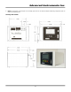
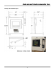
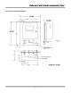
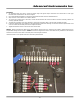
Gas Connections
The GPR-1600MS with its standard flow through configuration is designed for positive
pressure samples and requires connections for incoming sample and outgoing vent lines, see
illustrations above. The user is responsible for calibration gases and the required components,
see below. Flow rates of 1-3 SCFH cause no appreciable change in the oxygen reading. A flow
indicator with an integral metering valve upstream of the sensor is recommended as a means
of controlling the flow rate of the sample gas. A flow rate of 1 SCFH is recommended for
optimum performance.
Caution: Do not place your finger over the fitting designated as the vent (it pressurizes the
sensor) or to test the flow indicator when gas is flowing to the sensor. Removing your finger
(the restriction) generates a vacuum on the sensor and may damage the sensor (voiding the
sensor warranty).
Procedure:
1. Caution: Do not change the factory setting until instructed.
2. Regulate the pressure and flow as described in Pressure & Flow above.
3. Install the sample out or vent line connection to the 1/8” dia. fitting labeled SAMPLE VENT.
4. Install the incoming sample or span gas line to the 1/8” dia. fitting labeled SAMPLE IN.
5. Set the flow rate to 1 SCFH (open the flow control valve completely if using an external sampling pump positioned
downstream of the sensor).
6. Allow gas to flow through the analyzer for 3-5 minutes and proceed to Calibration or Sampling.