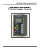
Advanced Instruments Inc.. GPR-2000 / GPR-2000 P Portable Oxygen Analyzer Owner’s Manual 2855 Metropolitan Place, Pomona, CA 91767 USA ♦ Tel: 909-392-6900, Fax: 909-392-3665, e-mail: info@aii1.com, www.aii1.
Advanced Instruments Inc.
Advanced Instruments Inc. 2 Quality Control Certification Date _________ Model Customer _______________________ Order No.
Advanced Instruments Inc. 3 General Safety & Installation Safety This section summarizes the basic precautions applicable to all analyzers. Additional precautions specific to individual analyzer are contained in the following sections of this manual. To operate the analyzer safely and obtain maximum performance follow the basic guidelines outlined in this Owner’s Manual.
Advanced Instruments Inc. Installation Gas Sample Stream: Ensure the gas stream composition of the application is consistent with the specifications and review the application conditions before initiating the installation. Consult the factory to ensure the sample is suitable for analysis. Note: In natural gas applications such as extraction and transmission, a low voltage current is applied to the pipeline itself to inhibit corrosion.
Advanced Instruments Inc. Flow rates of 1-5 SCFH cause no appreciable change in the oxygen reading. However, flow rates above 5 SCFH generate backpressure and erroneous oxygen readings because the diameter of the integral tubing cannot evacuate the sample gas at the higher flow rate. The direction the sample gas flows is not important, thus either tube fitting can serve as the inlet or vent – just not simultaneously.
Advanced Instruments Inc. Moisture and/or particulates generally can be removed from the sensor by opening the sensor housing and either blowing on the the sensing surface or gently wiping or brushing the sensing surface with damp cloth. Caution: Minimize the exposure of ppm sensors to air during this cleaning process. Air calibration followed by purging with zero or a gas with a low ppm oxygen concentration is recommended following the cleaning process.
Advanced Instruments Inc. Electronics The signal generated by the sensor is processed by state of the art low power micro-processor based digital circuitry. The first stage amplifies the signal. The second stage eliminates the low frequency noise. The third stage employs a high frequency filter and compensates for signal output variations caused by ambient temperature changes. The result is a very stable signal. Sample oxygen is analyzed very accurately.
Advanced Instruments Inc. Accuracy & Calibration Single Point Calibration: As previously described the galvanic oxygen sensor generates an electrical current proportional to the oxygen concentration in the sample gas. Absolute Zero: In the absence of oxygen the sensor exhibits an absolute zero, e.g. the sensor does not generate a current output in the absence of oxygen. Given these linearity and absolute zero properties, single point calibration is possible.
Advanced Instruments Inc. Zero Calibration In theory, the galvanic fuel cell type oxygen has an absolute zero meaning it produces no signal output when exposed to an oxygen free sample gas.
Advanced Instruments Inc. Span Calibration Span Calibration involves adjusting the transmitter electronics to the sensor’s signal output at a given oxygen standard. Maximum drift from calibration temperature is approximately 0.11% of reading per °C. The frequency of calibration varies with the application conditions, the degree of accuracy required by the application and the quality requirements of the user. However, the interval between span calibrations should not exceed three (3) months.
Advanced Instruments Inc. Mounting the Analyzer Normally mounting a portable analyzer is not a consideration. However, the GPR-2000 Series analyzers can operate continuously when connected to AC power using the appropriate charging adapter. The analyzer enclosure is cast with four (4) holes in the bottom section specifically intended for wall mounting.
Advanced Instruments Inc. Installing the Oxygen Sensor GPR-2000 Series Portable Oxygen Analyzers are equipped with an integral oxygen sensor. They are fully operational from the shipping container with the oxygen sensor installed, tested and calibrated by the manufacturer prior to shipment. Should it be necessary to install the oxygen sensor – see section 6 Maintenance which covers replacing the oxygen sensor.
Advanced Instruments Inc. Establishing Power to the Electronics The analyzer is fully operational from the shipping container with the oxygen sensor installed and calibrated at the factory prior to shipment. Once installed, we recommend the user allow the analyzer to stabilize for 10-15 minutes and then recalibrate the device as instructed below. Establish power to the analyzer electronics by pushing the red ON/OFF key. The digital display responds instantaneously.
Advanced Instruments Inc. Main Menu Access the MAIN MENU by pressing the MENU key: MAIN MENU AUTO SAMPLE MANUAL SAMPLE CALIBRATION Range Selection The analyzer is equipped with four (4) standard measuring ranges (see specification) and provides users with a choice of sampling modes. By accessing the MAIN MENU, users may select either the AUTO SAMPLING (ranging) or MANUAL SAMPLING (to lock on a single range) mode.
Advanced Instruments Inc. MAIN MENU AUTO SAMPLE MANUAL SAMPLE CALIBRATION 4. 5. 6. MANUAL RANGE >>> 25% 10% 5% 1% Advance the reverse shade cursor using the ARROW keys to highlight the desired MANUAL RANGE. Press the ENTER key to select the highlighted menu option. The following displays appears with the range selected and oxygen concentration of the sample gas: 3.3% MANUAL RANGE 25% 10% 5% 1% >>> MANUAL SAMPLING 5 % RANGE 24.5 C 7. 8. The display will not shift automatically.
Advanced Instruments Inc. Zero Calibration In theory, the galvanic fuel cell type oxygen has an absolute zero meaning it produces no signal output when exposed to an oxygen free sample gas.
Advanced Instruments Inc. MAIN MENU AUTO SAMPLE MANUAL SAMPLE CALIBRATION 4. 5. 6. CALIBRATION SPAN CALIBRATE ZERO CALIBRATE DEFAULT SPAN DEFAULT ZERO OUTPUT SPAN OUTPUT ZERO >>> Advance the reverse shade cursor using the ARROW keys to highlight DEFAULT ZERO. Press the ENTER key to select the highlighted menu option. The following display appears and after 3 seconds the system returns to the SAMPLING mode: 3.3% FACTORY DEFAULTS SET AUTO SAMPLING 10 % RANGE 24.
Advanced Instruments Inc. 7. Compute the adjustment value as described in Appendix B or consult the factory. The true adjustment value must be determined empirically by trial and error. Adjust the initial adjustment value for additional percent errors. 090.0 OUTPUT ZERO OFFSET PRESS UP OR DOWN TO CHANGE VALUE ENTER TO SAVE MENU TO RETURN 8.
Advanced Instruments Inc. ¾ Calibrating with a span gas approximating 5-10% of the full scale range near the expected oxygen concentration of the sample gas is acceptable but less accurate than ‘optimum calibration accuracy’ method recommended – the method usually depends on the gas available. ¾ Calibrating at the same 5-10% of the full scale range for measurements at the higher end of the range (example: calibrating an Oxygen Purity Analyzer in air at 20.
Advanced Instruments Inc. Procedure - Span Calibration: This procedure assumes the span gas is under positive pressure. Caution: The user must ascertain that the oxygen reading (actually the sensor’s signal output) has reached a stable value before initiating the SPAN CALIBRATE function. Failure to do so will result in an error. For calibration purposes, use of the AUTO SAMPLE mode is recommended.
Advanced Instruments Inc. 19. Press the ENTER key to select the highlighted menu option. GAS CONCENTRATION PERCENT PPM 20. The following displays appear: 000.00 PERCENT PRESS UP OR DOWN TO CHANGE VALUE ENTER TO SAVE MENU TO RETURN 080.00 PERCENT >>> SPAN CALIBRATION ENTER TO CALIBRATE MENU TO ABORT 21. Press the ENTER key to advance the underline cursor right or press the MENU key to advance the underline cursor left to reach to the desired digit of the alarm value. 22.
Advanced Instruments Inc. Procedure Air Calibration – Without Integral Pump: 1. Review the above Span Calibration procedure and the following instructions before proceeding: (a) Range selection and menu operation – note steps #7-9 and #28-29 do not apply. (b) Section 6 Maintenance – instructions for removing the sensor explain how to expose the sensor to ambient air. 2. Access the interior of the analyzer by removing the four (4) screws securing the front panel of the analyzer. 3.
Advanced Instruments Inc. MAIN MENU AUTO SAMPLE MANUAL SAMPLE CALIBRATION CONFIG ALARMS BYPASS ALARMS 4. 5. 6. CALIBRATION >>> SPAN CALIBRATE ZERO CALIBRATE DEFAULT SPAN DEFAULT ZERO OUTPUT SPAN OUTPUT ZERO Advance the reverse shade cursor using the ARROW keys to highlight DEFAULT SPAN. Press the ENTER key to select the highlighted menu option. The following display appears 100.0 OUTPUT SPAN OFFSET PRESS UP OR DOWN TO CHANGE VALUE ENTER TO SAVE MENU TO RETURN 7.
Advanced Instruments Inc. Sampling Analyzers (GPR-2000) without the optional integral sampling pump: Require positive pressure to flow the sample gas by the sensor to measure the oxygen concentration in a sample gas. Analyzers (GPR-2000P) equipped with the optional integral sampling pump: Place the sampling pump’s toggle switch in the ON position to draw the sample gas into the analyzer or place the sampling pump’s toggle switch in the OFF position and follow the GPR-2000 procedure above.
Advanced Instruments Inc. 6 Maintenance With exception of components related to optional equipment and charging the battery of portable analyzers, cleaning the electrical contacts when replacing the sensor is the extent of the maintenance requirements of this analyzer as there are no serviceable parts in the analyzer given the nature of the solid state electronics and sensor. Serviceability: Except for replacing the oxygen sensor, there are no parts inside the analyzer for the operator to service.
Advanced Instruments Inc. Warning indicators: An LED indicator located on the front panel will light continuously during the CHARGE cycle. A second LED indicator located on the front panel provides a blinking 72 hour warning LOW BATT of the need to recharge the battery. Caution: Operating the analyzer beyond this 72 hour warning may permanently damage the battery. 7 Spare Parts Recommended spare parts for the GPR-2000 Series Portable Oxygen Analyzer: Item No.
Advanced Instruments Inc. 9 Warranty The design and manufacture of Advanced Instruments Inc. oxygen analyzers and oxygen sensors are performed under a certified Quality Assurance System that conforms to established standards and incorporates state of the art materials and components for superior performance and minimal cost of ownership.
Advanced Instruments Inc. 10 MSDS – Material Safety Data Sheet Product Identification Product Name Oxygen Sensor Series - PSR, GPR, AII, XLT Synonyms Electrochemical Sensor, Galvanic Fuel Cell Manufacturer Analytical Industries Inc., 2855 Metropolitan Place, Pomona, CA 91767 USA Emergency Phone Number 909-392-6900 Preparation / Revision Date January 1, 1995 Notes Oxygen sensors are sealed, contain protective coverings and in normal conditions do not present a health hazard.
Advanced Instruments Inc. Spill or Leak Steps if material is released Sensor is packaged in a sealed plastic bag, check the sensor inside for electrolyte leakage. If the sensor leaks inside the plastic bag or inside an analyzer sensor housing do not remove it without rubber or latex gloves and safety glasses and a source of water. Flush or wipe all surfaces repeatedly with water or wet paper towel (fresh each time). Disposal In accordance with federal, state and local regulations.
Advanced Instruments Inc.
Advanced Instruments Inc. Output Zero Procedure: 1. Access the MAIN MENU by pressing the MENU key. 2. Advance the reverse shade cursor using the ARROW keys to highlight CALIBRATION. 3. Press the ENTER key to select the highlighted menu option and the following displays appear: MAIN MENU AUTO SAMPLE MANUAL SAMPLE CALIBRATION CONFIG ALARMS BYPASS ALARMS 4. 5.
Advanced Instruments Inc. 4. 5. Advance the reverse shade cursor using the ARROW keys to highlight OUTPUT SPAN. Press the ENTER key to select the highlighted menu option and the following display appears: 100.0 OUTPUT SPAN OFFSET PRESS UP OR DOWN TO CHANGE VALUE ENTER TO SAVE MENU TO RETURN 6. 7. 8. 9. Enter the adjustment value as follows . . .
Advanced Instruments Inc.
Advanced Instruments Inc.