
User Manual

Advanced Instruments Inc.
13
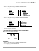
6. The 4-20mA current output is obtained by connecting the current measuring device between the positive and negative
terminals labeled OUTPUT 4-20mA.
7. To check the signal output of the 4-20mA E/I integrated circuit connect an ammeter as the measuring device and confirm
the output is within +
0.1mA of 4mA.
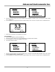
8. Caution: To assure proper grounding, connect the 4-20mA signal output to the external device (PLC, DCS, etc.) before
attempting any zero or span adjustments.
Installing the Oxygen Sensor
The GPR-2800AIS Oxygen Transmitter is equipped with an integral oxygen sensor. It has been tested and calibrated by the
manufacturer prior to shipment and are fully operational from the shipping container.
Caution: All transmitters must be calibrated once the installation has been completed and periodically thereafter as described
below. Following the initial installation and calibration, allow the transmitters to stabilize for 24 hours and calibrate with certified
span gas.
Caution: DO NOT open the oxygen sensor. The sensor contains a corrosive liquid electrolyte that could be harmful if touched
or ingested, refer to the Material Safety Data Sheet contained in the Owner’s Manual appendix. Avoid contact with any liquid or
crystal type powder in or around the sensor or sensor housing, as either could be a form of electrolyte. Leaking sensors should
be disposed of in manner similar to that of a common battery in accordance with local regulations.
Procedure – Optional Sensor Housing:
1. The sensor has not been installed at the factory (in standard configuration there are no
valves to isolate the sensor) and it will be necessary to install the sensor in the field.
2. Caution: Do not change the factory settings until instructed to do in this manual.
3. Connect the gas lines as previously described.
4. Purge the oxygen trapped in the newly connected gas lines for 3-5 minutes.
5. Flow zero gas or sample gas with a low % oxygen concentration to the analyzer at the
predetermined flow rate of 2 SCFH.
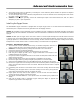
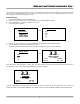
6. Using the 5/16 wrench supplied loosen but do not remove the clamp bolt located under the
sensor housing, see photo.
7. Rotate the upper section of the sensor housing 90º to disengage from the clamp.
8. Remove the upper section by pulling it straight up and place it on a smooth surface.
9. Select the AUTO RANGING option from the SAMPLE menu with gas flowing to the analyzer.
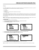
10. Remove the oxygen sensor from the bag and remove the red shorting device (including the gold
ribbon) from the PCB located at the rear of the sensor. Minimize the time the sensor is exposed
to ambient air.
11. Immediately place the sensor in the bottom section of the sensor housing with the PCB facing
up.
12. Immediately place the upper section of the sensor housing over the sensor, gently push the
upper section downward and rotate 90º to engage the clamp.
13. Finger tighten the clamp bolt and then tighten it one full turn with the 5/16 wrench to
securely lock the two sections of the sensor housing.
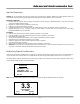
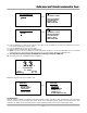
14. The analyzer will OVER RANGE for a short period of time as indicated by the graphical LCD
display.
15. Wait until the display shows a meaningful oxygen reading and begins to approach the
expected oxygen content of the sample gas.