Advanced Instruments Inc. GPR-2900 Oxygen Analyzer Owner’s Manual 2855 Metropolitan Place, Pomona, California 91767 USA ♦ Tel: 909-392-6900, Fax: 909-392-3665, e-mail: info@aii1.
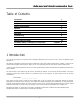
Advanced Instruments Inc. Table of Contents Introduction 1 Quality Control Certification 2 Safety 3 Features & Specifications 4 Operation 5 Maintenance 6 Spare Parts 7 Troubleshooting 8 Warranty 9 Material Safety Data Sheets 10 Correlating readings - LCD display to 4-20mA output Drawings Appendix B A/R 1 Introduction Your new oxygen analyzer is a precision piece of equipment designed to give you years of use in variety of industrial oxygen applications.
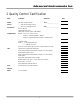
Advanced Instruments Inc. 2 Quality Control Certification Date: Customer: Order No.
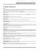
Advanced Instruments Inc. 3 Safety Guidelines General This section summarizes the essential precautions applicable to the GPR-2900 Oxygen Analyzer. Additional precautions specific to individual analyzer are contained in the following sections of this manual. To operate the analyzer safely and obtain maximum performance follow the basic guidelines outlined in this Owner’s Manual.
Advanced Instruments Inc. Maintenance Serviceability: Except for replacing the oxygen sensor, there are no parts inside the analyzer for the operator to service. Only trained personnel with the authorization of their supervisor should conduct maintenance. Oxygen Sensor: DO NOT open the sensor. The sensor contains a corrosive liquid electrolyte that could be harmful if touched or ingested, refer to the Material Safety Data Sheet contained in the Owner’s Manual appendix.
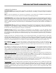
Advanced Instruments Inc. 5 Operations Principle of Operation The GPR-2900 Oxygen Analyzer incorporates a variety of percentage range advanced galvanic fuel cell type sensors. This model is configured for panel mounting and requires a 6”W x 3”H cutout with 4 holes for the studs located on the back side of the analyzer’s front panel. Optional mounting configurations include a 19” rack or wall mount enclosure with or without a sample system. Contact the factory for additional information on options.
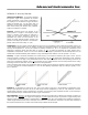
Advanced Instruments Inc. Calibration & Accuracy Overview Single Point Calibration: As previously described the galvanic oxygen sensor generates an electrical current proportional to the oxygen concentration in the sample gas. In the absence of oxygen the sensor exhibits an absolute zero, e.g. the sensor does not generate a current output in the absence of oxygen. Given these linearity and absolute zero properties, single point calibration is possible.
Advanced Instruments Inc. Recommendation 1: Zero calibration, see Determining True Zero Offset below, is recommended only for online analyzers performing continuous analysis below 5% of the lowest most sensitive range available with a ppm analyzer, e.g. analysis below 0.5 ppm on the 10 ppm range, or below 0.1% (1000 ppm) with a percent analyzer.
Advanced Instruments Inc. Installation Considerations Gas Sample Stream: Ensure the gas stream composition of the application is consistent with the specifications and review the application conditions before initiating the installation. Consult the factory if necessary to ensure the sample is suitable for analysis. Note: In natural gas applications such as extraction and transmission, a low voltage current is applied to the pipeline itself to inhibit corrosion.
Advanced Instruments Inc.
Advanced Instruments Inc. Recommendations to avoid erroneous oxygen readings and damaging the sensor: ¾ Do not place your finger over the vent (it pressurizes the sensor) to test the flow indicator when gas is flowing to the sensor. Removing your finger (the restriction) generates a vacuum on the sensor and may damage the sensor (voiding the sensor warranty).
Advanced Instruments Inc. Gas Connections: The GPR-2900 with its standard flow through configuration is designed for positive pressure samples and requires connections for incoming sample and outgoing vent lines. The user is responsible for calibration gases and the required components, see below. Flow rates of 1-5 SCFH cause no appreciable change in the oxygen reading.
Advanced Instruments Inc. 4. 5. 6. 7. To connect to an active relay or “fail safe”, connect the live cable to the common terminal C and the secondary cable to the normally open NO terminal. To break the connection upon relay activation, connect the secondary cable to the normally closed NC terminal. Insert the stripped end of the cables into the appropriate terminal slots assuring no bare wire remains exposed that could come in contact with the back panel of the analyzer enclosure.
Advanced Instruments Inc. Installing the Oxygen Sensor The GPR-2900 Oxygen Analyzer is equipped with an external oxygen sensor. They have been tested and calibrated by the manufacturer prior to shipment and are fully operational from the shipping containers. The sensor has not been installed at the factory and it will be necessary to install the sensor in the field. Caution: DO NOT open the oxygen sensor.
Advanced Instruments Inc. Establishing Power to the Electronics: Once the power to the electronics is established, the digital display responds instantaneously. When power is applied, the analyzer performs several diagnostic system status checks termed “START-UP TEST” as illustrated below: START-UP TEST ELECTRONICS – PASS TEMP SENSOR – PASS BAROMETRIC SENSOR – PASS REV. 1.61 Note: The analyzer display defaults to the sampling mode when 30 seconds elapses without user interface. 3.
Advanced Instruments Inc. Note: For calibration purposes, use of the AUTO SAMPLE mode is recommended. However, the user can select the full scale MANUAL SAMPLE RANGE for calibration as dictated by the accuracy of the analysis required – for example, a span gas with an 8.0% oxygen concentration with the balance nitrogen would dictate the use of the 0-10% full scale range for calibration and a 0-5% or 0-1% measuring ranges. Auto Sampling: 1. Access the MAIN MENU by pressing the MENU key. 2.
Advanced Instruments Inc. 9. Once the OVER RANGE warning appears the user must advance the analyzer to the next higher range via the menu and keypad Press MENU, select MANUAL SAMPLING, press ENTER, select the appropriate MANUAL RANGE and press ENTER again. Alarms The CONFIG ALARMS features a system that can be configured in the field.
Advanced Instruments Inc. 10. Note: The PERCENT alarm value is entered with one decimal, the PPM alarm value is entered as an integer. 01.0 GAS CONCENTRATION SET ALARM 1 VALUE PERCENT PPM >>> PRESS UP OR DOWN TO CHANGE VALUE ENTER TO SAVE MENU TO RETURN 002 GAS CONCENTRATION SET ALARM 1 VALUE PERCENT PPM >>> PRESS UP OR DOWN TO CHANGE VALUE ENTER TO SAVE MENU TO RETURN 11.
Advanced Instruments Inc. Set Alarm Delay: Once the values for ALARM 1 and ALARM 2 have been entered, the user may elect to delay the activation of the local alarms and relay contacts for up to 99 minutes. This feature allows users to distinguish between transient occurrences and true upset conditions. This feature can be particularly useful on remote applications without affecting the 4-20mA signal output. 1. Access the MAIN MENU by pressing the MENU key. 2.
Advanced Instruments Inc. MAIN MENU MAIN MENU AUTO SAMPLE MANUAL SAMPLE CALIBRATION CONFIG ALARMS BYPASS ALARMS 5. 6. >>> SET ALARM 1 SET ALARM 2 SET ALARM DELAY ALARM 1 HI/LO ALARM 2 HI/LO ALARMS AUDIBLE/SILENT Advance the reverse shade cursor using the ARROW keys to highlight the ALARM 1 option, which appears as either ALARM 1 HI or ALARM 1 LO. Press the ENTER key to toggle and change the displayed setting. After 3 seconds, the system returns to SAMPLING mode. 3.3% AUTO SAMPLING 10 % RANGE 24.
Advanced Instruments Inc. Bypass Alarms: This feature, separate from CONFIG ALARMS above, enables the user to disable the local audible alarm and relay contacts during calibration or servicing. The alarms are enabled when the alarm condition is corrected. 1. Access the MAIN MENU by pressing the MENU key. 2. Advance the reverse shade cursor using the ARROW keys to highlight BYPASS ALARMS. 3. The following displays appears: MAIN MENU AUTO SAMPLE MANUAL SAMPLE CALIBRATION CONFIG ALARMS BYPASS ALARMS 4.
Advanced Instruments Inc. Zero Calibration In theory, the oxygen sensor produces no signal output when exposed to an oxygen free sample gas.
Advanced Instruments Inc. 0.000 PPM ZERO CALIBRTION ENTER TO CALIBRATE MENU TO ABORT 8. 9. Press the ENTER key to calibrate or MENU key to abort and return to SAMPLING mode. Allow approximately 60 seconds for the calibration process while the processor determines whether the signal output or reading has stabilized within 50% of the full scale low range. 10.
Advanced Instruments Inc. Output Zero: In rare instances the 4-20mA signal output may not agree to the reading displayed by the LCD. This feature enables the user to adjust the 4mA signal output when the LCD displays 00.00. Compute the adjustment value as described in Appendix B or consult the factory. Note: Adjust the 20mA signal output with the OUTPUT SPAN option described below. The true adjustment value must be determined empirically by trial and error.
Advanced Instruments Inc. Span Calibration Maximum drift from calibration temperature is approximately 0.11% of reading per °C. The analyzer has been calibrated at the factory. However, in order to obtain reliable data, the analyzer must be calibrated at the initial start-up and periodically thereafter. The maximum calibration interval recommended is approximately 3 months, or as determined by the user’s application.
Advanced Instruments Inc. 3.3% MAIN MENU AUTO SAMPLE MANUAL SAMPLE CALIBRATION CONFIG ALARMS BYPASS ALARMS 5. 6. 7. 8. 9. AUTO SAMPLING 10 % RANGE 24.5 C LO1 2% Return to the MAIN MENU by pressing the MENU key. Advance the reverse shade cursor using the ARROW keys to highlight CALIBRATION. Press the ENTER key to select the highlighted menu option. Repeat to select SPAN CALIBRATE The following displays appear: MAIN MENU AUTO SAMPLE MANUAL SAMPLE CALIBRATION CONFIG ALARMS BYPASS ALARMS 10. 11. 12. 13.
Advanced Instruments Inc. 23. Save the adjustment value by pressing the ENTER key or abort by pressing the MENU key. 24. Allow approximately 60 seconds for the calibration process while the processor determines whether the signal output or reading has stabilized within 60% of the full scale low range. Both the Zero Calibrate and Span Calibrate functions result in the following displays: PASSED CALIBRATION FAILED CALIBRATION OR 25.
Advanced Instruments Inc. Output Span: In rare instances the 4-20mA signal output may not agree to the reading displayed by the LCD. This feature enables the user to adjust the 20mA signal output should the LCD display not agree. Note: Adjust the 4mA signal output with the OUTPUT ZERO option described above. Procedure: 1. Access the MAIN MENU by pressing the MENU key. 2. Advance the reverse shade cursor using the ARROW keys to highlight CALIBRATION. 3.
Advanced Instruments Inc. Sampling GPR-2900 Oxygen Analyzer requires positive pressure to flow the sample gas by the sensor to measure the oxygen concentration in a sample gas. If not available see Pressure & Flow section. Note: Prematurely initiating the ZERO CALIBRATION procedure can cause the analyzer to display a negative reading in both the ZERO and SAMPLE modes. Prematurely initiating the SPAN CALIBRATION procedure can cause erroneously high offsets and inaccurate readings.
Advanced Instruments Inc. 6 Maintenance There are no moving parts in the analyzer given the modular nature of the electronics and sensor. Cleaning the electrical contacts when replacing the sensor is the extent of the maintenance requirements of this analyzer. Sensor Replacement: Periodically, the oxygen sensor will require replacement. The operating life is determined by a number of factors that are influenced by the user and therefore difficult to predict.
Advanced Instruments Inc. 8 Troubleshooting Symptom Possible Cause Recommended Action Reading does not reflect expected values Sensor was not calibrated at the pressure, flow rate and temperature anticipated in the sample gas stream Recalibrate the analyzer using the known oxygen content of ambient air, 20.9%, and if the sensor responds we should presume it is correct.
Advanced Instruments Inc. 9 Warranty The design and manufacture of GPR Series oxygen analyzers, monitors and oxygen sensors are performed under a certified Quality Assurance System that conforms to established standards and incorporates state of the art materials and components for superior performance and minimal cost of ownership.
Advanced Instruments Inc. 10 MSDS Material Safety Data Sheet Product Identification Product Name Oxygen Sensor Series - PSR, GPR, AII, XLT Synonyms Electrochemical Sensor, Galvanic Fuel Cell Manufacturer Analytical Industries Inc., 2855 Metropolitan Place, Pomona, CA 91767 USA Emergency Phone Number 909-392-6900 Preparation / Revision Date January 1, 1995 Notes Oxygen sensors are sealed, contain protective coverings and in normal conditions do not present a health hazard.
Advanced Instruments Inc. Spill or Leak Steps if material is released Sensor is packaged in a sealed plastic bag, check the sensor inside for electrolyte leakage. If the sensor leaks inside the plastic bag or inside an analyzer sensor housing do not remove it without rubber or latex gloves and safety glasses and a source of water. Flush or wipe all surfaces repeatedly with water or wet paper towel (fresh each time). Disposal In accordance with federal, state and local regulations.
Advanced Instruments Inc. Appendix B Correlating Readings - LCD Display and 4-20mA Output In rare instances the 4-20mA signal output may not agree to the reading displayed by the LCD. The Output Zero and Output Span features enable the user to adjust the 4mA signal output to correlate with the reading displayed by the LCD. For optimum accuracy make two separate adjustments as follows: 1. OUTPUT ZERO feature: To adjust the 4mA signal output and requires zero gas. 2.
Advanced Instruments Inc. 100.0 OUTPUT ZERO OFFSET PRESS UP OR DOWN TO CHANGE VALUE ENTER TO SAVE MENU TO RETURN 14. Enter the calculated adjustment value. Note: Once the initial adjustment is made and checked at the PLC it may be necessary to fine tune the initial adjustment by repeating. Any additional percent error must be added or subtracted from the initial adjustment value 000.0 OUTPUT ZERO OFFSET PRESS UP OR DOWN TO CHANGE VALUE ENTER TO SAVE MENU TO RETURN 15.
Advanced Instruments Inc. 27. Enter the calculated adjustment value, refer to example described above. Note: Once the initial adjustment is made and checked at the PLC it may be necessary to fine tune the initial adjustment by repeating. Any additional percent error must be added or subtracted from the initial adjustment value 064.0 OUTPUT SPAN OFFSET PRESS UP OR DOWN TO CHANGE VALUE ENTER TO SAVE MENU TO RETURN . 28.