
User manual

AMD2000 Series - Servo Drive - User Manual
132 DS619-0-00-0019 - Rev 0 ANCA Motion
P-0-1232 / 34000
Motor Thermal Rise Time
P-0-1233 / 34001
Power Stage Thermal Rise Time
P-0-1234 / 34002
Motor I2R Overload Warn Level
P-0-1235 / 34003
Power Stage I2R Overload Warn Level
AMD2000 Drive Amplifier
Motor Control
Torque Feedback Value (S-0-0084)
Velocity Feedback Value (S-0-0040)
Velocity Command Value (S-0-0036)
Torque Command Value (S-0-0080)
Position Command Value (S-0-0047)
Master Control Word (S-0-0137)
Primary Operating Mode (S-0-0032)
Secondary1 Operating Mode (S-0-0033)
Secondary2 Operating Mode (S-0-0034)
Secondary3 Operating Mode (S-0-0035)
Secondary4 Operating Mode (S-0-0284)
Secondary6 Operating Mode (S-0-0286)
Secondary7 Operating Mode (S-0-0287)
Secondary5 Operating Mode (S-0-0285)
M
S
S
Torque
Torque
or
Force
Motion
Motion
Current
Estimation
Encoder data
Scale or Encoder data
Driven Axis
Powertrain (ie.
gears, screws
etc)
Power Source
(1F, 3F)
Voltage
Switching
Mains Power
S
S
Current U
Current W
Field
Estimation
Encoder Selection and
Estimation of Position
& Velocity
Position
Controller
Velocity
Controller
Torque
Controller
Current
Controller
(q-axis)
Current
Controller
(d-axis)
v
d
v
q
Σ
Σ
i
d
i
q
Σ
Σ
Torque
Estimator
Operating
Mode
Arbitration
Additive Torque Command (S-0-0081)
Additive Velocity Command (S-0-0037)
Σ
Additive Position Command (S-0-0048)
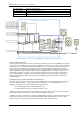
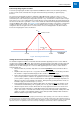
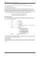
Figure 10-21 Servo controllers in the AMD2000 nested according to IEC 61800-7-2.
Torque and Current Control
As previously mentioned, torque and current commands are virtually synonymous in the AMD2000, except in the
special case where Field Weakening may apply to a PMSM type of motor. As a consequence of this, it should be
evident from Figure 10-22 that an external entity may gain access to setting torque commands, and thereby be
able to affect current commands. The torque control loop takes either a torque command from the velocity
control loop output or an externally originating NC torque command via IDN S-0-0080/80. This command can be
further modified by the simple addition of an offset torque using IDN S-0-0081 / 81. Details for how to select
whether NC or velocity control is the source of the torque commands is presented elsewhere in this manual
under “Operating Modes.” In addition, up to five notch filters and/or one low-pass filter may be applied to the
torque command signal, the details of which can be found elsewhere in this manual under the title “Torque
Command Filters.”
Configuring Torque and Current Controllers by Motor Type
The current control and torque control techniques for the Primary mode are selected via (P-0-503 / 33271) and
(P-0-222 / 32990) respectively. By choosing to fill in these IDN with one of the following two values, the
appropriate techniques are selected for application in the Motor Control;
10 = Permanent Magnet Servo Motor (PMSM) control, or
15 = Induction Motor Velocity over Frequency (IM V/F) control.
Similarly, the current control and torque control techniques for the Secondary1 mode can be selected using the
same values placed into IDN’s P-0-507 / 33275 and P-0-228 / 32996, respectively.
In addition to the above settings which need to be varied depending on the type of motor being driven, the motor
commutation technique must also be selected by filling in IDN P-0-506 / 33274 with the correct value. Once
again the user selects from either of the two values given above for the appropriate motor.