
User manual


AMD2000 Series - Servo Drive - User Manual
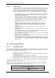
48 DS619-0-00-0019 - Rev 0 ANCA Motion
AMD2000 9A Drive 6.8.12.1.3
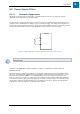
Use an Armature Bracket in order to terminate the shielded cable assembly.
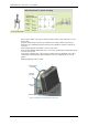
The Armature Termination Bracket assembly consists of the following parts :
1. Armature Termination Bracket
2. EMC Saddle Clamp
3. 2 x M5 screws
Please see accessories section for bracket ordering details. 13.4.13 Armature Shield Clamping
Brackets
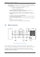
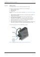
Clamp the Armature Termination Bracket down as shown below using the 2 x M4 screws.
Tightening Torque 2.5Nm max.
Carefully remove the Armature cable sheath to expose the metal braid. Expose
approximately 25mm of braid length.
The position of the exposed braid is to coincide with the EMC Saddle Clamp and the
metal bracket as shown below in order to provide sufficient contact for termination.
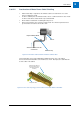
Tighten the Saddle Clamp screw to 0.5Nm as recommended by the manufacturer.
Fit the armature plug into the armature connector on the drive.
Ensure that the Armature Cable Earth wire is connected to an M5 ring lug or M5 spade lug
and connect to the bracket as shown below. Maximum tightening torque is 1.5Nm.
See below for the interactions for the shielded armature termination.
Armature Cable
Assembly
Exposed Braid
Armature Cable
Earth Wire
Protective
Earth Wire to
the Cabinet
Earth Bar
Termination
Bracket
EMC Saddle
Clamp
Figure 6-11 AMD2000 D2009 Drive Shield and Protective Earth Connection