
User manual

Power Wiring
ANCA Motion DS619-0-00-0019 - Rev 0 53
6
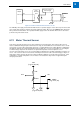
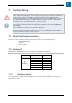
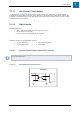
Relay:
Normally
Open
Motor
AMD2000
CN4/X4
24V
DI-01
20 or 21
7
Separate Customer
24V DC supply
24V 0V
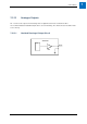
Figure 6-17: Motor Thermal Switch interface circuit
The 24V DC power supply for the thermal switch must be a separate supply as it can often carry noise that could
cause erratic drive operation, and may not provide sufficient isolation. Do not use the AMD2000 24V supply from
X4 to power the thermal switch. The separate 24 V DC supply used for the thermal switch can also be used to
power the relay in the brake circuit.
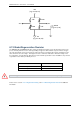
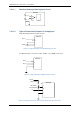
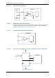
6.12 Motor Thermal Sensor
Some motors provide a thermal sensor to give feedback of motor temperature. This model of drive does not
feature a dedicated analogue input for this function. If using an external CNC, the motor thermal sensors can be
connected to one of the drive analog inputs by means of a voltage divider or two voltage dividers as indicated in
the diagrams and have the monitoring implemented in the CNC. The user is then responsible for converting the
non-linear voltage output from the circuit into an equivalent temperature for the temperature sensor
selected. Two temperature sensors are recommended as in diagram (x) in a bridge configuration instead of one
sensor. The reasons for this is increased noise immunity because there is twice as much voltage per degree of
temperature change, and also because the voltage feeding the divider does not affect the measurement. If this
configuration is used the temperature sensors must be co-located; that is they must be in approximately the
same physical location.
24V
(e.g. Pin 20, X4)
KTY84
3.9k
Ain+ Ain-
AGND
(e.g. Pin 3, X4)
0V
(e.g. Pin 46, X4)