Trademarks ANCEL is the trademark of Shenzhen OBDSPACE TECHNOLOGY CO., LTD All other marks are trademarks or registered trademarks of their respective holders. Copyright Information ©2019 Shenzhen OBDSPACE TECHNOLOGY CO., LTD All rights reserved. Disclaimer The information, specifications and illustrations in this manual are based on the latest information available at the time of printing. ANCEL reserves the right to make changes at any time without notice. Visit our website at www.anceltech.
One-Year Limited Warranty Subject to the conditions of this limited warranty, OBDSPACE TECHNOLOGY CO., LTD (“ANCEL”) warrants its customer that this product is free of defects in material and workmanship at the time of its original purchase for a subsequent period of one (1) year.
DAMAGES, LOSS OF USE OF THE PRODUCT OR ANY ASSOCIATED EQUIPMENT, COST OF CAPITAL, COST OF ANY SUBSTITUTE EQUIPMENT OR FACILITIES, DOWNTIME, THE CLAIMS OF ANY THIRD PARTIES, INCLUDING CUSTOMERS, AND INJURY TO PROPERTY, RESULTING FROM THE PURC HASE OR USE OF THE PRODUCT OR ARISING FROM BREACH OF THE WARRANTY, BREACH OF CONTRACT, NEGLIGENCE, STRICT TORT, OR ANY OTHER LEGAL OR EQUITABLE THEORY, EVEN IF ANCEL KNEW OF THE LIKELIHOOD OF SUCH DAMAGES.
Safety Information For your own safety and the safety of others, and to prevent damage to the device and vehicles, read this manual thoroughly before operating your scanner. The safety messages presented below and throughout this user’s manual are reminders to the operator to exercise extreme care when using this device. Always refer to and follow safety messages and test procedures provided by vehicle manufacturer. Read, understand and follow all safety messages and instructions in this manual.
Table of Contents ONE-YEAR LIMITED WARRANTY.............................................................................................................................2 SAFETY INFORMATION.............................................................................................................................................. 4 SAFETY MESSAGE CONVENTIONS USED.............................................................................................................................................
5.2.4.2 Custom List........................................................................................................................................25 5.2.5 Special Functions......................................................................................................................................26 6 STEERING ANGLE SENSOR (SAS) CALIBRATION........................................................................................28 7 OBDII/EOBD OPERATIONS.......................................
1 Using This Manual We provide tool usage instructions in this manual. Below is the conventions we used in the manual. 1.1 Bold Text Bold text is used to highlight selectable items such as buttons and menu options. Example: Press the ENTER button to select. 1.2 Symbols and Icons 1.2.1 Solid Spot Operation tips and lists that apply to specific tool are introduced by a solid spot ●. Example: When Settings is selected, a menu that lists all available options displays.
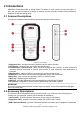
2 Introductions AD610Plus Professional ABS & Airbag Reset Tool works on most vehicles on the road today. It does not only have extensive coverage of vehicles but also provides accurate and professional diagnosis of ABS and airbag faults. 2.1 Scanner Descriptions This section illustrates external features, ports and connectors of the scanner. ® Figure 2-1 Front View 1 Diagnostic Port - provides connection between vehicle and the scanner. 2 LCD Display - shows menus, test results and operation tips.
print data. 4 Nylon Carry Pouch - stores the scanner and its accessories. 2.3 Technical Specifications Display: Back lit, 240*320 TFT color display Working Temperature: 0 to 60 ℃ (32 to 140℉) Storage Temperature: -20 to 70℃(-4 to 158℉) Power Supply: 8-18V vehicle power and 3.3V USB power Dimensions: (L*W*H): 200*100*38mm Weight: 0.
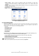
ABS & Airbag - leads to screens for diagnostic trouble code information, live data, ECU information and special functions of ABS and airbag systems on 49 vehicle makes sold worldwide. ● Settings - leads to screens for adjusting default settings to meet your own preference and view information about the scanner. ● Data Manager - leads to screens for access to data records. ● Update - leads to screen for updating the scanner. ● Figure 3-1 Sample Home Screen 3.
Figure 3-2 Sample Input Text Screen 2. Scroll with the arrow keys to highlight your desired letter or number and press the ENTER key to confirm. Figure 3-3 Sample Numeric Keyboard Screen 3. To delete a letter or number, use the function key Cursor Forward to move the cursor to it and then press the Backspace button. 4. When finished the entry, press Completed key to continue. 4.
4.1 Auto VIN Auto VIN is a shortcut for VIN reading menu which typically includes following options: ● Automatic ● VIN acquisition Manual input VIN 4.1.1 Automatic VIN Acquisition Automatic VIN Acquisition allows to identify a vehicle by automatically reading the vehicle identification number (VIN). To identify a vehicle automatic VIN reading: 1. Scroll with the arrow keys to highlight Auto VIN from the main menu and press the ENTER key. Figure 4-1 Sample Main Menu Screen 2.
Figure 4-3 Sample Automatic VIN Reading Screen 4. Answer YES if the Vehicle Specification or VIN code is correct and a menu of controller selection displays. Answer NO if it is incorrect, and you are required to enter the correct VIN number manually. Figure 4-4 Sample Manual VIN Entry Screen 5. If it takes too long to get the VIN code, press Cancel to stop and input the VIN manually. Or if failed to identify the VIN, please input the VIN manually or click Cancel to quit.
Figure 4-6 Sample Main Menu Screen 2. Select Manually input VIN from the menu, and press the ENTER key. Figure 4-7 Sample VIN Reading Screen 3. Press the function key Keyboard and a virtual keyboard opens for VIN entry. Figure 4-8 Sample Manual VIN Entry Screen 5. Input a valid VIN code and use the function key Completed to confirm. The scan tool starts to identify the vehicle. 4.
4.2.1 SmartVIN SmartVIN allows to identify a vehicle by automatically reading the vehicle identification number (VIN). To identify a vehicle by SmartVIN: 1. Scroll with the arrow keys to highlight ABS & Airbag from main menu and press the ENTER key to start. If you have the application assigned to one of the function keys at the bottom of the screen, you can alternatively press the function key to start the application. Figure 4-9 Sample Main Menu Screen 2.
4. Select SmartVIN from the menu, and press the ENTER key. Figure 4-12 Sample VIN Reading Screen 5. The scan tool starts to communicate with the vehicle and read the Vehicle Specification or VIN Code automatically. Figure 4-13 Sample Automatic VIN Reading Screen 6. Answer YES if the Vehicle Specification or VIN code is correct and a menu of controller selection displays. Answer NO if incorrect, and you are required to enter the correct VIN number manually. Figure 4-14 Sample Manual VIN Entry Screen 4.
1. Refer to step 1-3 of 4.2.1 SmartVIN. 2. On each screen that appears, select the correct option and then press the ENTER key. Do this until the complete vehicle information is entered and the menu of controller selection displays.
Figure 5-2 Sample Quick Scan Screen 3. At the end of successful automatic controller scan, a menu with a list of installed controllers together with their DTC overview displays. Figure 5-3 Sample Quick Scan Screen 4. If there is diagnostic trouble code(s) detected in a control unit, press the function key corresponding with Report on the screen to view details of code information. Or press the function key Erase to clear them. Figure 5-4 Sample DTC Screen 5.
Figure 5-5 Function Menu screen 5.1.2 Control Modules Control Modules screen displays all controllers available on the vehicles. The controllers listed on the menu do not mean that they are installed on the vehicle. To select a system for testing: 1. Scroll with the arrow keys to highlight Control Modules from the menu and press the ENTER key. A controller menu displays. Figure 5-6 Sample Control Module Menu Screen 2. Select the system you would like to test.
5.2 Diagnostic Operations After a system is selected and the scanner establishes communication with the vehicle, the Function Menu displays. The menu options may include: ● ECU information ● Read Codes ● Clear Codes ● Live Data ● Special Functions NOTE Not all function options listed above are applicable to all vehicles. Available options may vary by the year, model, and make of the test vehicle. 5.2.
Present/Permanent/Current Codes Pending Codes ● History Codes ● ● Present/Permanent/Current codes stored in a control module are used to help identify the cause of a trouble or troubles with a vehicle. These codes have occurred a specific number of times and indicate a problem that requires repair. Pending codes are also referred to as maturing codes that indicate intermittent faults. If the fault does not occur within a certain number of drive cycles (depending on vehicle), the code clears from memory.
Figure 5-12 Freeze Data screen Freeze Frame Data: a snapshot of critical vehicle operating conditions automatically recorded by the on-board computer at the time of the DTC set. It is a good function to help determine what caused the fault. 4. Use left and right arrow keys to scroll back and forth through different screens of data. 5. Press function key Save to store freeze frame information. Or use the BACK key to exit. 5.2.
Figure 5-14 Sample Clear Codes Screen 3. Check the codes again. If any codes remain, repeat the Clear Codes steps. 5.2.4 Live Data Live Data menu lets you view and record real time PID data from a selected vehicle electronic control module. Menu options typically include: ● Complete ● Custom List List 5.2.4.1 Complete Data List Complete List menu lets you view all live PID data from a selected system. To view live PID data: 1.
Figure 5-16 Sample Live Data Menu Screen 3. Scroll with the up and down arrow keys to highlight a line, and left and right arrow keys to scroll back and forth through different screens of data. Press function key Pause to suspend collecting data from the vehicle and use the Start key to resume collecting data. To record data to memory of the scanner, use the function key SAVE, and press Stop Saving to stop recording at anytime. Figure 5-17 Sample Live Data Screen 4.
Figure 5-19 Sample Two PID Graph Screen 6. Press the function key Merge Graph to display two PID plots in one coordinate to check how they affect each other. Figure 5-20 Sample Merge Graph Screen 7. Press the Back key to return to the previous menu. 5.2.4.2 Custom List Custom List menu lets you to minimize the number of PIDs on the data list and focus on any suspicious or symptom-specific data parameters. To create a custom data list: 1. Select Custom List from the menu and press the ENTER key.
2. The custom data selection screen displays. Scroll with the up and down arrow keys to highlight a line, press the ENTER key and then repeat the action to make more selections. To deselect an item, select it again and then press the ENTER key. Alternatively, use the function keys Select All and Deselect to select or deselect all items at once. Figure 5-22 Sample Custom List Selection Screen 3. When finished selection, use the function key OK to display selected items.
IMPORTANT Before bleeding the brake system, make sure no diagnostic codes are present. Do not let the master cylinder run dry during the brake bleeding procedure. After bleeding the brake system, check the brake pedal for excessive travel or a “spongy” feel. Bleed again if either condition is present. ● Automated Test - automatically commands each solenoid valve and the pump motor on and off to test for proper operation.
Figure 5-24 Sample Function Menu Screen 2. A group selection screen, test selection screen, several step-by-step instruction screens, or bidirectional control screen may appear. Read the screens and follow all instructions. If necessary, use the function keys to perform commands or answer any questions. If more than 3 function keys displays, use up and down arrow keys to select a command and press the ENTER key to confirm. Figure 5-25 Sample Special Function screen 3.
Figure 6-2 Sample SAS Calibration Screen 7 OBDII/EOBD Operations OBDII/EOBD menu lets you access all OBD service modes. According to ISO 9141-2, ISO 14230-4, and SAE J1850 standards, the OBD application is divided into several sub programs, called ‘Service $xx’.
8 System Setup This section illustrates how to program the scanner to meet your specific needs. When Settings is selected, a menu with available service options displays. Menu options typically include: Language Unit ● Shortcuts ● Display Test ● Keypad Test ● About ● ● 8.1 Select Language Selecting Language opens a screen that allows you to choose system language. The scan tool is set to display English menus by default. To configure system language: 1.
8.2 Change Units Selecting Unit opens a dialog box that allows you to choose units of measure. To change the unit setup: Scroll with the arrow keys to highlight Units from Settings menu and press the ENTER key. Figure 8-3 Sample Settings Screen 1. Press the up and down arrow key select an item and press the ENTER key to save andreturn. Figure 8-4 Sample Unit Selection Screen 8.3 Configure Shortcut Keys Selecting Shortcuts option lets you to change the functionality of the shortcut buttons.
Figure 8-5 Sample Settings screen 2. Press the up and down arrow key select a shortcut key and press the ENTER key. A screen with a list of loaded applications displays. Figure 8-6 Sample Shortcuts Screen 3. Scroll with the arrow keys to highlight an application and press the ENTER key to assign the application to the shortcut key Figure 8-7 Sample Shortcuts Screen 32 AD610 Plus ABS & Airbag Reset Tool Manual_English_V1.
8.4 Display Test Selecting Display Test option opens a screen that allows you to check the functionality of the display. To test the display: 1. Scroll with the arrow keys to highlight Display Test from Settings menu and press the ENTER key to start test. Check if there are any missing spots in the LCD screen. 2. xFigure 8-8 Sample LCD Test ScreenTo quit the test, press the Back key. 8. 5 Keypad Test Selecting Keypad Test option opens a screen that allows you to check the functionality of the keypad.
Figure 8-10 Sample Keypad TestScreen 3. To quit the test, press Back key twice. 8.6 Tool Information Selecting About option opens a screen that shows information about your scan tool, such as serial number, which may be required for product registration. To view information of your scan tool: 1. Scroll with the arrow keys to highlight About from Settings menu and press the ENTER key Figure 8-11 Sample Settings Screen 2. A screen with detailed information of the scanner displays.
3. Press the Back key to exit. 9 Update The scanner can be updated to keep you stay current with the latest development of diagnosis. This section illustrates how to register and update your scan tool. To update your scanner, please follow the three steps as below: Step1: Obtain an ANCEL ID. Step2: Register the product with the product serial number. Step3: Update the product by the update application AncelScanner. For step 1 and 2, you can also go to our site with the link below.