Assembly Instructions 100’ and 120’ Wide Multi-piece Systems NEW CENTURY® TENT Please read all assembly / installation instructions before the installation or removal of this product. SALES OFFICES: 1100 BURCH DRIVE PO BOX 3477 EVANSVILLE, IN 47733 USA WEB EC4615 PHONE: 812-867-2421 FAX: 812-867-0547 1-800-544-4445 EMAIL: tents@anchorinc.com www.anchorinc.
IMPORTANT: The installation of this Century Tent should be performed/supervised by knowledgeable tent installers with a clear understanding of safety issues as well as the methods of anchoring. The requirements as specified with blue print (supplied by Anchor Industries Inc.) must be followed. The installer/owner must read the assembly instructions completely prior to any installation. Particular attention must be given to anchoring! See Caution Statement on back page of this manual.
Parts Illustrations (cont’d APPROVED SIDE AND CENTER POLES LENGTH Side Short Center Long Center (120’ Tent only) SIZE 8’ Alum. 2” Sch. 40 Pipe Alum. 2 1/2” Sch. 40 Pipe Alum. 3” Fluted Alum. 3” Kedar Trac Fluted 10’ Alum. 2 1/2” Sch. 40 Pipe Alum. 3 1/2” Fluted Alum. 3 1/2” Kedar Trac Fluted 12’ Alum. 2 1/2” Sch. 40 Pipe Alum. 3 1/2” Fluted Alum. 3 1/2” Kedar Trac Fluted 37’ Alum. 8” Ctr. Pole Assy. Alum. 7” Fluted Assy. 39’ Alum. 8” Ctr. Pole Assy. Alum. 7” Fluted Assy. 41’ Alum. 8” Ctr.
1 WEB GUY LAYOUT* Multi-pc -100’ with 30’ Mid MARK LOCATION OF STAKES, SIDE POLES & CENTER POLES 90’-0’ TENT LINE ** To find diagonal measurement: diagonal = width² + length² Field 1B Field 7 REQUIRED DISTANCE BETWEEN SIDE POLES AND STAKE LINES: 7’ POLE STAKE OUT 5’-3” 8’ POLE STAKE OUT 6’-0” 10’ POLE STAKE OUT 7’-6” Field 1A WEB GUY WITH 2’ STAKE BAR AND (3) 42” STAKES (TYP. AS SHOWN) Field 3B (2) WEB GUYS WITH 4’ STAKE BAR AND (6) 42” DBL. HEAD STAKE (TYP.
WEB GUY LAYOUT* Multi-pc -100’ with 40’ Mid MARK LOCATION OF STAKES, SIDE POLES & CENTER POLES 100’-0’ TENT LINE ** To find diagonal measurement: diagonal = width² + length² Field 1B Field 2 Field 1A REQUIRED DISTANCE BETWEEN SIDE POLES AND STAKE LINES: 7’ POLE STAKE OUT 5’-3” 8’ POLE STAKE OUT 6’-0” 10’ POLE STAKE OUT 7’-6” SE TO DIA * * SQ GO 14 U NA 1’-5 AR L ” E DIM LA E YO N U SIO T N Field 3A Field 4 WEB GUY WITH 2’ STAKE BAR AND (3) 42” STAKES (TYP.
WEB GUY LAYOUT* Multi-pc -120’ with 40’ Mid MARK LOCATION OF STAKES, SIDE POLES & CENTER POLES 100’-0’ TENT LINE ** To find diagonal measurement: diagonal = width² + length² Field 1B Field 2 REQUIRED DISTANCE BETWEEN SIDE POLES AND STAKE LINES: 7’ POLE STAKE OUT 5’-3” 8’ POLE STAKE OUT 6’-0” 10’ POLE STAKE OUT 7’-6” Field 1A CENTER POLES (TYP.) N BAR AND (3) 42” STAKES (TYP.
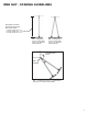
WEB GUY - STAKING GUIDELINES REQUIRED DISTANCE BETWEEN SIDE POLES AND STAKE LINES: 8’ POLE STAKE OUT 6’ 0” 10’ POLE STAKE OUT 7’ 6” 12’ POLE STAKE OUT 9’ 0” (1) WEB GUY WITH 2’ STAKE BAR AND (3) 42” DOUBLE HEAD STAKES (2) WEB GUYS WITH 4’ STAKE BAR AND (6) 42” DOUBLE HEAD STAKES CORNER WEB GUYS TENT CORNER (2) WEB GUYS WITH (2) 2’ STAKE BARS AND (6) 42” DOUBLE HEAD STAKES 7
2 TENT SECTION LAYOUTS Spread drop cloths. Properly orient tent sections by placing bundles at spots marked “X” and unroll in the direction of the arrows on the following diagrams. Caution: Any objects with sharp projections which must remain on site under the tent should be padded and taped.
Layout 120’ x 100’ Century (40’ Mid) 3 Lacing With tent sections on ground, overlap rings at center pole holes with grommet side on top. Starting at end opposite long loop, lace between center pole holes first. Push first loop up through corresponding grommet.
Lacing (cont’d) Continue lacing process. Attach ridge snap to ring as you come to them. (100’ wide tents only) Tie off last long loop. Cover lacing by joining protective flaps using Maxi Grip tool. Secure flap with buckles at top and bottom. Then lace from center pole to eave on both sides of tent. Tie off last long loop. Align plates and attach hook on inside of tent as shown. Attach two guy webs through both plates. Lace all sections of tent.
Alternate for Optional 8” Center Pole Set top weldment in center pole hole and connect to overlapping rings with shackles provided. attach with hitch pin Place assembled pole cap over pipe of top weldment. Attach hinge pin to pipe extending through top of pole cap. Rotate pole cap to align holes in pipes. Note: Pole cap assembly is illustrated on a separate sheet packed with fabric top.
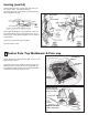
7 Raise Center Poles Important Information to prevent/minmize tent damage prior to center poles being erected. 1. Traditionally, raising all side poles prior to pushing center poles is acceptable, however, during a high wind install, only raise the side poles as needed on the side of the tent that the center poles are being pushed from. This helps to eliminate wind damage. 2.
7 Raise Center Poles cont’d Assemble center poles with base plates. Raise center poles with top pointing downwind. With bottom of center pole in bucket of front end loader, slowly guide top of pole under tent with installers as shown. At center pole hole connect top weldment to pole with bolt, washer, and nut. Continue guiding top of pole to prevent snagging of fabric. Slowly raise top of pole as high as possible by hand while moving forward with loader.
Alternate method using Pole Sled (for use with fork truck or front end loader with pallet fork attachment). Using the pole sled makes it possible to keep the center pole steadily attached to a loader with pallet forks. The tent is still put up in the same manner as already outlined. Connect chain with shackles to loader to prevent detachment. Slide forks into rectangular tubes. Center Pole Pole Sled must be purchased separately.
EVANSVILLE, INDIANA PHONE NUMBER 812· 867· 2421 FAX NUMBER 812· 867· 0547 Anchor products are of superior design and operate best within the parameters of these instructions. It is imperative that the instructions be carefully read and COMPLETELY FOLLOWED. Please read installation instructions before the installation or removal of this product. Installation instructions are available online at www.anchorinc.com or by calling 1-800-544-4445. CAUTION: 1.