Anchor AN-3668 Video Intercom System User's and Installation Manual KP-800C/AN-3668/GS-001 Please read this manual carefully and save for future reference.
Contents 1. 2. 3. 4. 5. 6. Introduction Operating Instructions 2 5 2.1 Instructions for the AN-3668 Room Station Operation 2.2 Instructions for the KP-800C Entrance Station Operation 5 6 Conduit Tubing 7 3.1 Conduit Tubing Layout 3.2 Conduit Tubing Tips 3.3 Pulling the Wires 7 7 Interface Wiring Other Wiring Installation 6.1 6.2 6.3 6.4 6.5 7. 8.
1: Introduction Thank you for purchasing the Anchor Security System's AN-3668 Video Intercom system. We are sure that once you have started using it, you will find that it is a very convenient and reliable system, designed to make the process of protecting your home, business, or factory a little easier. Before we begin with the installation and setup instructions, we would like to explain the concepts behind each component of the system.
building, they simply have to press the DOOR OPEN button. The KP-800C Entrance Stations consist of a CCD camera, a microphone, a keypad, and an LED display. A guest coming to visit a building would simply enter the code number for the house he or she wants to visit and wait for the host to answer the call. IN U S E O p e r a tio n In s tr u c tio n 1 .K e y in re s id e n t‘ s d ig it c o d e a n d p re ss “ C a ll” . 2 .
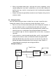
Direct Input Input by Resistance Blue Yellow Power Brown LED Video Output AC Power Fuse (6 ports) Input AN-VDA6 Video Signal Amplifier Control Signal Connector Line AC Power input DC Power output PW-108 Power Supply In addition to these items, a system may also contain a Guard Station and various other types of security options, such as Gas Leak Detectors, Door and Window Alarms, and Panic Buttons.
2:Operating Instructions 2.1 Operation Instructions for Room Station Speaker Hole 4" LCD "Door Open" Indicator LED Receive Magnetic Hook "Open Door" Button Magnetic Hook "Monitor" Button Microphone "Call" Button Handset Contrast Knob Power / Volume Knob Brightness Knob Fig. 2.1 The Room Station a. After a guest has arrived, entered a code on the entrance station, then pressed the CALL button, the room station will emit a Ding-Dong sound, and the screen will turn on, showing an image of the guest.
2.2 Operation Instructions for Entrance Station Host Station Code LED Display Lens Infra-Red Illumination LEDs IN U S E O p e r a tio n I n s tr u c tio n 1 .K e y in r e s id e n t ‘ s d ig it c o d e a n d p r e s s “ C a ll” . 2 .I n t h e n e v e n t o f e r r o r ,p re s s “ C le a r ” a n d k e y in c o r r e c t n u m b e rs . 3 .R e s id e e n t s m u s t p re s s “ C a ll” b e fo r e k e y in g in p e r s o n a l e n t r y a c c e s s c o d e . 4 .
3: Conduit Tubing 3.1 Conduit Tubing Layout Before any system can be installed or hooked up, the first step is to install conduit tubing to protect the wiring. This step should be at the same time the building is under construction, as it will be difficult to install the tubing once the building has been completed. Here are the basic guidelines for selecting and installing the tubing: a. b.
3/4“ 3/4“ Approx. 30-40 cm from Room Station Pre-Installation Box . typical 90*60*40mm+ power box is suitable. Each floor must have a extension box. Recommended Size: 400 * 300 * 100 mm 1“ 3/4“ 3/4“ Ground Floor Distribution Box, must be 40x30x10cm or larger Distance from floor: 30-40cm 3/4“ 3/4“ Distance from floor: 120-140 cm Security Station Pre-Installation Box. Typical 90 * 60 * 40mm power box is suitable. Should be as close to the guard station as possible.
d. e. While using conduit tubing that is too large will cause no problem, using conduit tubing that is too small is a bad idea, as this will make it difficult to pull the wires up, as well as increasing the risk of insulation being rubbed off the wires. Keep in mind that the ground floor needs to have AC power wiring, for the entrance station. 3.3 Pulling the Wires After the conduit tubing has been installed, the next step is to pull the wires through the conduits.
Wiring Possibility 2: 3C Lines One 3C/2V One 9C Power Distribution Box Entrance Station Electronic Lock One 6C Central Control Guard Station Wire Specifications Diagram: Room Station Room Station Top Floor Distribution Box 3C/2V+8C 3C/2V+8C 3C/2V+ AC+8C Please Note: Ground Floor Distribution Box We suggest using wire diameter of at least 0.65mm Entrance Station or more for the control signal lines (6C or 9C).
4:Interface Wiring Terminator Box Brn./Yel./Blue Station 9 Insert Extra Final Room 5 6 7 8 10 11 12 Room Stations here Video Signal Resistance is usually 50 ~ 75 ohms. If the resistance in the system is not at this level, a resistor can be added here.
4:Interface Wiring Terminator Box Final Room Station Brn./Yel./Blue 5 6 7 8 9 Insert Extra 10 11 12 Room Stations here Video Signal Resistance is usually 50 ~ 75 ohms. If the resistance in the system is not at this level, a resistor can be added here.
5: Other Wiring The Anchor AN-668 uses two different types of wiring: Single Core ( the 9C wire used in the main conduit) and Multi Core (the 3C/2V used for power supply in the system). At several points during the wiring process, wires are required to be spliced together. When splicing two wires of the same type, we recommend twisting the two wires together, at least 7 times, and then using electrical tape to insulate the splice.
6: Installation 6.1 Pre-installation Before room station the unit itself, you must first install the Pre-Installation Box. This is the box that feeds the wiring into the unit, and that holds it in place on the wall. 6.2 Installation of the Entrance station We recommended placing the center of unit approximately 120-140cm (4’ - 4½’) above the ground. Please Note: a. If the unit will be exposed to rain, please use a rain cover and add any necessary protection. b.
6.3 Installation of the Room station We recommend placing the unit approximately 120cm-150cm (4’-5’) above the ground. Please note: C Avoid mounting the unit in places with excessive amounts of oil, smoke, or high temperatures, as these may have an effect on the quality and life of the unit. 6.4 Code Setting Board on the Room Station Instructions 1. The code number setting board for each room station corresponds to the entrance station display.
Code Setting Procedure DIP Switch Position Number represented Hexadecimal 0+0+0+0= 0 0 1+0+0+0= 1 1 0+2+0+0= 2 2 1+2+0+0= 3 3 0+0+4+0= 4 4 1+0+4+0= 5 5 Symbol Displayed 0+2+4+0= 6 6 1+2+4+0= 7 7 0+0+0+8= 8 8 1+0+0+8= 9 9 0+2+0+8=10 A 1+2+0+8=11 B 0+0+4+8=12 C 1+0+4+8=13 D 0+2+4+8=14 E Not Used 1+2+4+8=15 F Not Used 15 Not Used
6.5 1. Decoding Process When the room station receives a signal that matches it’s own identification code, it will automatically emit a ringing sound, and the display will be powered on.
2nd Digit 1st Digit 3rd Digit 1 ON = 0 OFF = 1 2 ON = 0 OFF = 2 = 2 3 ON = 0 OFF = 2 * 2 = 4 4 ON = 0 OFF = 2 * 2 * 2 = 8 Using these 4 switches, it is possible to make any combination from 0(all 4 ON)to 15(all 4 OFF), or 16 combinations. Setting the Code On the Entrance Station, there is a digital display for the code. We recommend using the first digit to represent the address, the second and third digits for the floor.
7: Detailed Wiring Diagram 7.
7.2 KP-800C CONNECTOR EXPLAIN KP-800C CONNECTOR EXPLAIN FORM NAME EXPLAIN 9 PIN FEMALE CONNECTOR CONNECT TO ROOM STATION 6 PIN FEMALE CONNECTOR CONNECT TO GUARD STATION 6 PIN MALE CONNECTOR CONNECT TO PW-104 AND ELECTRONIC LOCK 4 PIN SELECT JUMPER SHORT: ONLY ONE KP-800 OPEN: TWO OR MORE KP-800 OR GUARD STATION EXIT 2 PIN VIDEO SELECT CONNECTOR CONNECT TO AS-001-1 (ONLY ONE KP-800) PS: The explain of connector are standard for connect on KP-800C.
7.2 KP-800C CONNECTOR EXPLAIN KP-800C CONNECTOR EXPLAIN FORM NAME EXPLAIN 9 PIN FEMALE CONNECTOR CONNECT TO ROOM STATION 6 PIN FEMALE CONNECTOR CONNECT TO GUARD STATION 6 PIN MALE CONNECTOR CONNECT TO PW-104 AND ELECTRONIC LOCK 4 PIN SELECT JUMPER SHORT: ONLY ONE KP-800 OPEN: TWO OR MORE KP-800 OR GUARD STATION EXIT 2 PIN VIDEO SELECT CONNECTOR CONNECT TO AS-001-1 (ONLY ONE KP-800) PS: The explain of connector are standard for connect on KP-800C.
7.3 KP-800C & AN-3668 STANDARD DIAGRAM + - PW-108 ENDING CONNECTOR 1 4 AC 220V/ 110V 6 COAXIAL CABLE (RG-58U) VDA DC JACK DC18V IN AN-3668 AN-3668 1 2 3 4 5 6 7 8 1 2 3 4 5 6 7 8 AC 220V/110V CABLE WIRE 0.
7.3 KP-800C & AN-3668 STANDARD DIAGRAM + - PW-108 ENDING CONNECTOR 1 4 AC 220V/ 110V 6 COAXIAL CABLE (RG-58U) VDA DC JACK DC18V IN AN-3668 AN-3668 5 6 7 8 9 10 11 12 5 6 7 8 9 10 11 12 AC 220V/110V CABLE WIRE 0.
8: Maintenance and Repair 8.1 Basic Troubleshooting The following is a checklist of simple procedures you can do to insure that your system functions properly. Make sure that the phone is on the hook when not in use. This should be a common thing to check first when trouble-shooting a system. Make sure that the system is getting power. As the system’s power supplies are all located in one place, it is quite simple to check and make sure that the system is getting power.
Please use the chart on page 25 for instructions on how to adjust the room station. Not Functioning? A. The Power switch is turned off. B. The power fuse is burned out. Does the C. The power to this area has been cut off. System have A. The DTR unit has failed. Is the system transmitting O B. The Microphone has failed. C. The handset wire is cut. D. The amplifier IC has failed. A. Room Station's code is incorrectly set. Does the room B. Volume setting is too low. station respond to a C.
9: Specifications 9.1 AN-3668S Room Station Power Source: DC +20V, 1 AMP. Power Consumption: Less Than 10 Watts Video Input: 1Vp-p NTSC/PAL (Factory Set) Audio Output: 0.5 Watt Time Use Limit: Approx. 60 seconds (+/- 10 seconds) Trigger Signal: Negative signal Resolution: More than 450 TV Lines Display: 4" Color TFT LCD Door Bell Sound: Ding-Dong Sound Max. Wiring Distance: 50 Meters / 0.65mm wire Max. No.
9-4 AD-020 Power Supply Power Source: Power Output: Dimensions: Weight: AC 110V or 220V (Factory Set) DC +20V, 1 AMP. 85mm(L) x 68mm(W) x 56mm(D) Approx. 650 g 10: Service Guarantee The products described in this manual come with a 1-year guarantee.