
Installation manual


21
8: Maintenance and Repair
8.1 Basic Troubleshooting
The following is a checklist of simple procedures you can do to insure that your system functions properly.
Make sure that the phone is on the hook when not in use. This should be a common thing to check first when
trouble-shooting a system.
Make sure that the system is getting power. As the system’s power supplies are all located in one place, it is
quite simple to check and make sure that the system is getting power.
Make sure that none of the wiring has come loose. This can be checked first by checking the wiring at the
main circuit board, by the power supplies, and then by dismounting the entrance station and the suspect room
station, to check the wiring their.
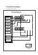
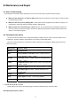
8.2 Checking System Wiring
The Anchor Intercom System uses a compromised design, making it easy for repair or service personnel to do
maintenance. All that is needed to find problems in the system is a basic Multi-meter.
Each wire in the system has no more than two states. Please see the chart below, explaining the function and
states of each wire:
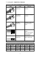
Wire (Color) Function / States
Brown System Ground
Red
Voice and Video control wire. Normal: +9VDC and above;
During Operation: +3VDC - +6VDC
Orange
Voice Line. Normal: +10VDC and above; During Operation:
+1VDC - +4VDC
Yellow
Independent Control Line. Normal: 0VDC; During Operation:
+2VDC - +5VDC
Green
Open Door Signal. Normal: 0VDC; During Operation: +5VDC
Blue
Door Open Light. Door Open: +20VDC and above; Door
Closed: 0VDC
Purple Not Used
Gray
Video Signal +. 0.2VAC - 1VAC during operation.
White
Video Signal -. Same as Brown(System Ground).
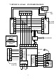
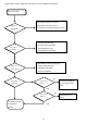
8.3 Troubleshooting the Room Station
Please use the flow chart on the following page to perform troubleshooting on the room station:
8.4 Adjusting the Entrance Station