
Use and Care Guide


— 19 —
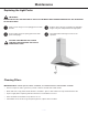
Assembly
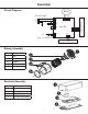
Circuit Diagram
Blower Assembly
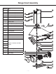
Electrical Assembly
u
v
w
x
Number Part
1 Junctionboxcover
2 Capacitor
3 Main PCB board
4 Junctionboxbottom
AC 120V 60Hz
Main PCB
L
N
E
Capacitor
MAX 10.2V 250mA 2.5W
CN6
CN5
CN1
CN2
CN4
CH B
CN3
Motor
CN8
+
_
LED Pucks
___
Controls PCB
u
v
y
x
w
u
v
w
x
Number Part
1 Grid
2 Motor
3 Impeller
4 Blower
5 Wind drum inlet
— 19 —
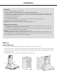
Electrical Assembly
u
v
w
x
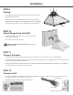
Blower Assembly
Number Part
1 Grid
2 Motor
3 Impeller
4 Blower
5 Wind drum inlet
u
v
y
x
w
Assembly
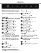
Circuit Diagram
Number Part
1 Junction box cover
2 Capacitor
3 Main PCB board
4 Junction box bottom
AC 120V 60Hz
Main PCB
L
N
E
Capacitor
MAX 10.2V 250mA 2.5W
Temperature / Humidity
Sensor
CN6
CN5
(Optional)
CN1
CN2
CN3
CN4
CH B
CN8
Motor
+
_
LED Pucks
___
Controls PCB