MODEL: WPP430 & WPP436 IMPORTANT SAFETY INSTRUCTIONS Carefully read the following important information regarding installation safety and maintenance. Keep these instructions for future reference.
IMPORTANT SAFETY NOTICE READ AND SAVE THESE INSTRUCTIONS READ ALL INSTRUCTIONS BEFORE INSTALLING AND OPERATING THIS APPLIANCE ● ● ● ● The installation in this manual is intended for qualified installers, service technicians or persons with similar qualified background. Installation and electrical wiring must be done by qualified professionals and in accordance with all applicable codes and standards, including fire-rated construction.
IMPORTANT SAFETY NOTICE READ AND SAVE THESE INSTRUCTIONS READ ALL INSTRUCTIONS BEFORE INSTALLING AND OPERATING THIS APPLIANCE WARNING: TO REDUCE RISK OF A RANGE TOP GREASE FIRE: a) Never leave surface units unattended at high settings. Boilovers cause smoking and greasy spillovers that may ignite. Heat oils slowly on low or medium settings. b) Always trun hood ON when cooking at high heat or when flambeing food (i.e. Crepes Suzette, Cherries Jubilee, Peppercorn Beef Flambé).
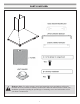
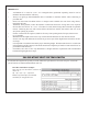
PARTS SUPPLIED: Hardware Note: For safety reasons, range hood mounting screws and anchors will not be included due to the variation of cabinetry constructions and wall material. Please consult your installation specialist regarding the optimal type of mounting screws and wall anchors to suit your home’s construction.
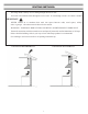
VENTING REQUIREMENTS: • • • • • • • HEIGHT & CLEARANCE: Vent system must terminate to the outside (Roof or side wall). DO NOT terminate the vent system in an attic or other enclosed area. DO NOT use 4” (10.2 cm) laundry-type wall caps. Use metal/aluminum vent only. Rigid metal/ aluminum vent is recommended. DO NOT use plastic vent. Always keep the duct clean to ensure proper airflow. Calculate the following figures before installation: 1. Distance from the floor to the ceiling 2.
IMPORTANT: • • • • • • • • A minimum of 6” round or 3-1/4 x 10” rectangular duct (purchased separately) must be used to maintain maximum airflow efficiency. Always use rigid type metal/aluminum ducts if available to maximize airflow when connecting to provided duct. Please use Duct Run Calculation below to compute total available duct run when using elbows, transitions and caps. ALWAYS, when possible, reduce the number or transitions and turns.
VENTING METHODS: • This range hood is factory set for venting through the roof or wall. • Vent work can terminate either through the roof or wall. To vent through a wall, a 90° elbow is needed. IMPORTANT: • NEVER exhaust air or terminate duct work into spaces between walls, crawl spaces, ceiling, attics or garages. All exhaust must be ducted to the outside.
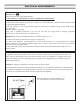
ELECTRICAL REQUIREMENTS: IMPORTANT: Observe all governing codes and ordinances. It is the customer’s responsibility to contact a qualified electrical installer. If codes permit and a separate ground wire is used, it is recommended that a qualified electrician determine that the ground path is adequate. A 120-Volt, 60 Hz, AC-only, fused electrical supply is required on a separate 15-amp circuit, fused on both sides of the line. DO NOT ground to a gas pipe.
PREPARATIONS: Advanced Preparations: • Be familiar with the controls of the range hood by reading through Range Hood Operations, Page 13. • Place the range hood on a flat, stable surface. Connect the range hood to a designated standard outlet (120-Volt, 60Hz, AC only) and turn on the range hood. Verify all operations of the range hood by referring to Range Hood Operations.
INSTALLATION: Installations (refer to Page 4 for parts): NOTE: Use threaded drywall anchors only when mounting the hood on sheet rock. Mounting the hood on wall studs or lumbars is highly recommended. Hardware Note: For safety reasons, range hood mounting screws and anchors will not be included due to the variation of cabinetry constructions and wall material. Please consult your installation specialist regarding the optimal type of mounting screws and wall anchors to suit your home’s construction.
INSTALLATION CONTINUE: Step 4: Venting • Fix the damper on the top vent of hood with 4 screws (requires screw C). If ventilation system is equipped with an external air duct with a different diameter, apply a reduction fitting. However, for maximum performance and safety, a 6” round ducting is recommended. (See Figure # 2) 3 2 Step 5: Mounting the hood on the wall • Hang the range hood on the hooks of the lower mounting bracket. (See Figure # 3) • Screw the range hood to the wall.
INSTALLATION CONTINUE: Step 6: Installing filters • To install filters for the following four steps (See Figure # 6): - Angle the filter into slots at the back of the hood. - Push the button on handle of the filter. - Release the handle once the filter fits into a resting position. - Repeat to install all filters. 6 Step 7: Test hood • Turn power On in control panel. • Check all lights and fan operations. • Make sure to leave this Installation Manual for the homeowner.
CONTROL PANEL OPERATION: Control Panel Layout and Buttons Configurations: Lights: Press the light button Power Settings: Press the to turn halogen lights on and off. once the motor starts to operate at low speed. Press the again and the motor will reach medium speed. once Press the again and the motor will reach high speed.
MOUNTING BRACKETS: Upper Chimney Bracket 5 1/8” (13 cm) 1 3/8” (3.5 cm) 8 21/32 (22 cm) Lower Chimney Bracket 7 7/8” (20 cm) 5 1/8” (13 cm) 1 3/8” (3.5 cm) 8 5/8” (21.
MEASUREMENTS AND DIAGRAMS: Height of range hood: 26” - 41 3/8” (66 cm -105 cm) The range hood can reach a 9’ ceiling if installed at 31” from cooktop. 8.77’’ (223mm) 6.81’’ (173mm) 15.74” - 31.10’’ (400 - 790 mm) 8.85’’ (225 mm) 1.37’’(35mm) 29.40’’ (747mm) 19.
TROUBLE SHOOTING: 1) If the range hood or halogen light does not operate after installation: • Check if the range hood has been plugged in, make sure that all power has been turned back ON,fused not blown and all electrical wiring are properly connected. 2) The range hood vibrates when the blower is on: • The range hood might not have been secured properly on to the ceiling or wall. 3) The blower or fan seems weak: • Check that the duct sized used is at least 6” or 3-1/4 x 10”.
RANGE HOOD ASSEMBLY: No.
SPECIFICATIONS: Body design Stainless steel Power Rating 120V / 60Hz (USA & Canada standard) cETLus Certified Total input power 235.1W Motor Input Power 230W Total Ampere 1.96A Levels of speed control 3 levels Interference Protection Radio frequency interference protected Air Flow 400 CFM Noise Level Low speed 50 dBA Number of Motor Single motor Fan Type Single chamber quiet Control Type Electronic control Filtration Type 2 x Aluminum filter Illumination 2 x 2.
BLOWER ASSEMBLY: No. 1 2 3 4 5 Description No. Description 6 Aluminum Cover 7 Plastic Wind Net 8 Sealing Gasket Blower Wind Wheel Nut Wind Wheel Motor Incabloc Rubber ELECTRICAL ASSEMBLY: No. 1 2 3 4 5 Description Electrical box bracket Electrical box base PCB Capacitor Electrical box cover No.
USE AND CARE INFORMATION: Operations: • Read and understand all instructions and warnings in this manual before operating the appliance. Save these instructions for future reference. • Always leave safety grills and filters in place. Without these components, operating fans could catch on to hair, fingers and loose clothing. • NEVER dispose cigarette ashes, ignitable substances, or any foreign objects into fans. • NEVER leave cooking unattended.