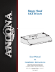
® Range Hood UC6 30 inch User Manual & Installation Instructions IMPORTANT SAFETY INSTRUCTIONS Carefully read the important information regarding installation, safety and maintenance. Keep these instructions for future reference.
Before You Begin INSTALLERS - Start Here Safety Instructions are on pages 4 to 6 and Installation Instructions are on pages 9 to 17. Please perform these steps: 1. Read the safety instructions. 2. Read all instructions in the Installation section of this manual BEFORE installing the range hood. 3. Remove all packing materials. 4. When finished, make sure to leave these instructions with the consumer. 5. Installation is to be done by a qualified technician only.
Table of Contents Before You Begin................................................................................................................................ 2 Table of Contents............................................................................................................................... 3 Important Safety Information............................................................................................................. 4 Included Parts..............................................
Important Safety Information READ ALL INSTRUCTIONS BEFORE USE Read and follow all instructions before using the range hood to prevent the risk of fire, electric shock, personal injury, or damage when using the range hood or appliances with the range hood. This guide does not cover all possible conditions that may occur. Always contact your service technician or manufacturer about problems that you do not understand.
Important Safety Information WARNING: TO REDUCE RISK OF A RANGE TOP GREASE FIRE: To reduce the risk of injury to persons in the event of a gas leaks: a) Never leave surface units unattended at high settings. Boilovers cause smoking and greasy spillovers that may ignite. Heat oils slowly on low or medium settings. • Extinguish any open flame. • DO NOT turn on the lights or any type of appliance. • Open all doors and windows to disperse the gas.
Important Safety Information WARNING: TO REDUCE RISK OF A RANGE TOP GREASE FIRE: 7. Two installers are recommended because of the large size and weight of this hood. 1. To reduce risk of fire and to properly exhaust air, be sure to duct air outside. Do not vent exhaust air into spaces within walls or ceilings or into attics, crawl spaces, or garages. 8. This product is equipped with a thermostat which may start blower automatically.
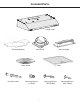
Included Parts Range Hood Rectangle bracket Vent-round Metal Cover Drywall anchors Vent-rectangle 2 Filters Mounting Screws (4 *8MM) Mounting Screws (ST4*30MM) —7— Mounting Screws (ST4*18MM)
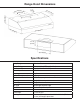
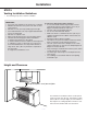
Range Hood Dimensions 8. (3 3 cm 1/4 in. ) 30 1/2 cm (12 in. ) 15 cm (5.9 in.) in.) m (10 25.4 c .) (5.9 in 15 cm 50 cm (19. 75 cm 6 in .) .) (29.5 in 8.3 cm (3 1/4 in.) 25.4 cm (1 0 in.) Specifications Body Design Power Rating Total Input Power Motor Input Power Amperage Speed Control Levels Interference Protection Motors Motor Type Fan type Control Filtration Illumination Venting Size Stainless Steel 120 V / 60 Hz (cETLus Certified) 140 W (140 W + 2*2.5 W) 135 W 1.
Installation STEP 1 Read the Safety Instructions • It is very important to read the safety instructions on pages 4, 5 and 6. IMPORTANT: It is the installer’s responsibility to comply with installation clearances. STEP 2 Unpack Range Hood and Prepare Tools • Carefully unpack the range hood and parts. Make sure all parts are included as shown on page 7. • DO NOT remove the protective film covering the appliance until the installation is fully completed.
Installation STEP 5 Venting Installation Guidelines • The following steps are for exterior ventilation. IMPORTANT: • Vent system must terminate to the outside (roof or side wall). • DO NOT terminate the vent system in an attic or other enclosed area. • DO NOT use 4 in. (10.2 cm) laundry-type wall caps. • Use metal/aluminum vent only. A rigid metal/aluminum vent is recommended. • DO NOT use a plastic vent. • Always keep the duct clean to ensure proper airflow.
Installation IMPORTANT: • A minimum of 6 in. (15.2 cm) round or 3-1/4 x 10 in. (25.4 cm x 8.3 cm) rectangular duct (purchased separately) must be used to maintain maximum airflow efficiency. • Always use rigid type metal/aluminum ducts if available to maximize airflow when connecting to provided duct. • Please use Duct Run Calculation below to compute total available duct run when using elbows, transitions and caps. • ALWAYS, when possible, reduce the number or transitions and turns.
Installation STEP 6 Preparations NOTE: To avoid damage to your hood, prevent debris from entering the vent opening. • Determine and mark the center line on the ceiling or wall where the range hood will be installed. • Make sure there is proper clearance within the ceiling or wall for exhaust vent. • Due to the weight and size of this unit, please make sure that the support system or framework being used is stable and secure in the ceiling or wall.
Installation • A metal cover is included, to protect the motor. To install, loosen and remove the 4 screws, then put the metal cover on and tighten the screws. Fig #3 STEP 9 Attaching Vent • There are 3 venting ways, with 2 type of damper options, one is 6” round, another is 3 1/4”x10” rectangle. NOTE: Please only punch the vent hole you want to use.
Installation Top venting using rectangular damper • If you require rectangular top (vertical) venting simply install the rectangular damper provided (See Fig #8, #9 and #10). Use screws 4 pcs 4*8MM to connect damper. Fig #8 Fig #9 Fix rectangle damper to the top by screws 4pcs 4*8MM Fig #10 Rear venting (horizontal) using rectangular damper • If you require rectangular top (horizontal) venting simply install the rectangular damper provided.
Installation STEP 10 Installing the Hood Method 1: Attaching the unit to the wall • The following drawings show the mounting dimensions of the 30” (750mm) . • Mark or drill 4 small holes on the mounting position according to the dimensions on Fig #14. • Insert 4 drywall anchors into the holes, and 2 screws ST4 *30MM into the top holes • Hang the range hood onto the screws. • Open the filter and install the inner panel in place with safety screws (ST4 *30MM).
Installation STEP 11 Venting • Depending on exterior ventilation chosen (see page 10), either exit the ducting through the ceiling or wall. • Always use rigid type metal/aluminum duct tube (follow the building codes in your area) to maximize airflow. Make sure that the backdraft flaps can open, to allow maximum airflow. Connect the duct tube to the vent/damper and securely seal with certified aluminum or foil tape so that it is air tight.
Installation STEP 12 Install Filters To install filters for the following four steps (See Figure #18): • Angle the filter into slots at the back of the hood. • Push the button on handle of the filter. • Release the handle once the filter fits into a resting position. • Repeat to install all filters.
Operation Stop Low Speed Medium Speed Power Settings Press the button once and the motor starts to operate at Low speed. u v Press the button speed. and the motor will reach Medium w Press the button speed. the motor will reach High x Press the button to turn the fan off. Lights u Press the light button off.
Maintenance Replacing the Light Bulbs IMPORTANT: ALWAYS SWITCH OFF THE ELECTRICITY SUPPLY AT THE MAIN PANEL BEFORE CARRYING OUT ANY OPERATION ON THE APPLIANCE. u Make sure the range hood is unplugged or turn OFF breaker. x Replace with a 4 Volt, 2.5Watt max, LED lights. Do not touch replacement bulb with bare hands! v w Open the filter and find the spring of the light. y Turn ON breaker and range hood to test for operation. Push the spring and the lights will slip out.
Range Hood Assembly Number — 20 — Part 1 Damper flap 2 Vent (rectangle) 3 Damper flap 4 Vent (round) 5 Rectangle bracket 6 Fixed cover 7 Motor housing 8 Motor bracket 9 Slot 10 11 Blower assembly (include motor) Wheel 12 Metal ring 13 Metal cover 14 Filter (1 set with 2pcs) 15 LED lights (1 set with 2pcs) 16 Screw bag 17 Control box 18 Controller assembly 19 Bracket of electronic box 20 Base of electronic box 21 Wiring connector 22 Capacitor 23 Transformer 24
Assembly Circuit Diagram Blower Assembly Number 1 2 Part Ring Blower 3 Propeller 4 Motor 5 Bracket of Motor Electrical Assembly Number 1 2 Part Screws Box 3 Transformer 4 Terminal 5 Box base 6 Connector 7 Capacitor — 21 —
Troubleshooting Problem Light on, but motor does not work Cause The motor blocked Solution Get rid of the blocking The capacitor is damaged Have capacitor replaced The motor bearings are jammed or damaged Have motor replaced Light does not work, motor does Beside the mentioned above, check the following: not work Light is damaged Replace lights Oil leakage Hood body shakes Wires are loose or disconnected Connect the wires as per the electric diagram The one-way valve and the air ventilation entr
Use and Care Information Operations • Read and understand all instructions and warnings in this manual before operating the appliance. Save these instructions for future reference. • Always leave safety grills and filters in place. Without these components, operating fans could catch on to hair, fingers and loose clothing. • NEVER dispose cigarette ashes, ignitable substances, or any foreign objects into fans. • NEVER leave cooking unattended.
Please register your product warranty by visiting the Ancona Home website. Canada & USA Phone: 1-888-686-0778 Fax: 800-350-8563 Email: service@anconahome.com Website: www.anconahome.com Ancona is in association with Mr Appliance for all after sales service calls. Please contact their service provider or visit their website: Phone: 1-888-998-2011 Website: www.mrappliance.com MAAN1248-01 © 2017 Copyright of Ancona Home. All rights reserved.