
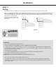
Use and Care Guide
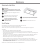

— 22 —
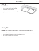
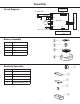
Assembly
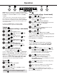
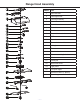
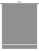
Circuit Diagram
Blower Assembly
Electrical Assembly
Number Part
1 Transformer
2 Base of electronic box
3 PCB
4 Capacitor
5 Cover of electronic box
Number Part
1 Bracket of motor
2 Motor
3 Blower
4 Propeller
AC 0V 60Hz12
Controls PCB
Main PCB
L
N
E
Capacitor
CN1
CN10
Motor
+
_
LED Pucks
MAX 10.2V 250mA 2.5W
CN8
Motor
Transformer
Temperature Humidity
Sensor
/
CN7
CN4
CN5
CN9
(Optional)