USER INSTRUCTIONS ODEL: 30 & 36 MODEL:MTRINA Under-Cabinet 5" High C1 Model IMPORTANT SAFETY INSTRUCTIONS Carefully read the following important information regarding installation safety and maintenance. Keep these instructions for future reference.
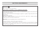
IMPORTANT SAFETY NOTICE READ ALL INSTRUCTIONS BEFORE INSTALLING AND OPERATING THIS APPLIANCE ● ● ● ● The installation in this manual is intended for qualified installers, service technicians or persons with similar qualified background. Installation and electrical wiring must be done by qualified professionals and in accordance with all applicable codes and standards, including fire-rated construction.
IMPORTANT SAFETY NOTICE READ ALL INSTRUCTIONS BEFORE INSTALLING AND OPERATING THIS APPLIANCE To reduce the risk of stove top grease fire: ● ● ● ● ● ● ● Keep all fans, filters, spacers, grease trays*, oil container* and grease-laden surfaces clean. Grease should not be allowed to accumulate on fan, filters, spacers, grease trays* and oil container*, and surfaces. Always turn range hood ON when cooking at high heat or when cooking flaming foods. Use high settings on cooking range only when necessary.
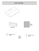
PARTS SUPPLIED: 4
VENTING REQUIREMENTS: • • • • • • • HEIGHT & CLEARANCE: Vent system must terminate to the outside (Roof or side wall). DO NOT terminate the vent system in an attic or other enclosed area. DO NOT use 4” (10.2 cm) laundry-type wall caps. Use metal/aluminum vent only. Rigid metal/ aluminum vent is recommended. DO NOT use plastic vent. Always keep the duct clean to ensure proper airflow. Calculate the following figures before installation: 1. Distance from the floor to the ceiling 2.
IMPORTANT: • • • • • • • • A minimum of 6” round or 3-1/4 x 10” rectangular duct (purchased separately) must be used to maintain maximum airflow efficiency. Always use rigid type metal/aluminum ducts if available to maximize airflow when connecting to provided duct. Please use Duct Run Calculation below to compute total available duct run when using elbows, transitions and caps. ALWAYS, when possible, reduce the number or transitions and turns.
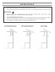
VENTING METHODS: • • This range hood is factory set for venting through the roof or wall. Vent work can terminate either through the roof or wall. To vent through a wall, a 90° elbow is needed. IMPORTANT: • • • • NEVER exhaust air or terminate duct work into spaces between walls, crawl spaces, ceiling, attics or garages. All exhaust must be ducted to the outside. Use metal/aluminum duct work only. Fasten all connections with sheet metal screws and tape all joints with certified aluminum or foil tape.
ELECTRICAL REQUIREMENTS: IMPORTANT: Observe all governing codes and ordinances. It is the customer’s responsibility to contact a qualified electrical installer. If codes permit and a separate ground wire is used, it is recommended that a qualified electrician determine that the ground path is adequate. A 120-Volt, 60 Hz, AC-only, fused electrical supply is required on a separate 15-amp circuit, fused on both sides of the line. DO NOT ground to a gas pipe.
PREPARATIONS: Advanced Preparations: • Be familiar with the controls of the range hood by reading through Range Hood Operations, Page 14. • Place the range hood on a flat, stable surface. Connect the range hood to a designated standard outlet (120-Volt, 60Hz, AC only) and turn on the range hood. Verify all operations of the range hood by referring to Range Hood Operations.
NEW INSTALLATION: ep 5: Venting Step 1: Create Exterior Ventilation • • • • Choose one of the exterior venting methods shown on Page 7. Create the exterior ventilation hole. Insert exterior damper into exterior ventilation hole. Following recommendations and calculations specified on Pages 5 to 9, use new aluminum/metal ducting cut specifically for the distance between the range hood damper and the exterior damper.
NEW INSTALLATION: Step 5: Installing the Hood Step 6: Venting certified aluminum or foil tape so that it is air tight. Please check the building codes in your city to learn which tape product is recommended. Step 7: Electrical Connection 5a) DON’T FORGET TO CONNECT THE GROUND! • Open the wiring compartment and secure the leads inside. • WARNING: ALL CONNECTORS MUST BE ENCLOSED IN THE WIRING COMPARTMENT. SAFETY WARNING: Risk of electrical shock. This range hood must be properly grounded.
REPLACEMENT INSTALLATION: 6 6 12
REPLACEMENT INSTALLATION: Step 5: Venting certified aluminum or foil tape so that it is air tight. Please check the building codes in your city to learn which tape product is recommended. Step 6: Electrical Connection 5a) DON’T FORGET TO CONNECT THE GROUND! • Open the wiring compartment and secure the leads inside. • WARNING: ALL CONNECTORS MUST BE ENCLOSED IN THEWIRING COMPARTMENT SAFETY WARNING: Risk of electrical shock. This range hood must be properly grounded.
CONTROL PANEL OPERATION: This range hood is equipped with six electronic controls, an Easy Clean Panel, two aluminum mesh filters with stainless steel panels, and two bright LED lights. The six electronic buttons control the intensity of the Lights, Speeds (Quiet, Low, Medium and High) and Power (On/Off). The Power Control (On/Off) offers startup, 3-minute delay or immediate power-off. The Light Control operates independently from the Power Control (On/Off) and is not affected by the delay shutoff.
REPLACING THE BULBS: Replacing the light bulbs: • This range hood uses halogen bulbs: 20W 12V type G4. • Make sure the range hood is unplugged or turn OFF breaker. • Place a flat-head screwdriver between light cover and housing to remove cover. • Gently pull defective bulb straight out and discard. • Wear a cotton glove or use a cloth to handle the replacement bulb. (DO NOT handle with bare fingers as this may shorten the life of the bulb). Push gently but securely into light socket.
MEASUREMENTS AND DIAGRAMS: 11 c m (4 3 /8 i n./p o.) o.) cm 8.3 .) po 16 c m m .4 c ./ 0 in cm (3 1 /4 in (1 ./po .) 25 (6 5 /16 in./ po. ) m 6c 65. 7/ (25 m 6c 30.5 cm (12 12 . 7 c m ( 5 i n . /p o . ) 34. 48 c m (19 25.4 in./ ( 13 5/ .) po ./ 8 in po. in./ ) 75 po. ) 8.3 cm cm .) po ./ 8 in 4.5 cm 2.5 ( 1 3 /4 i n . /p o . ) ./p in (1 ( 10 (3 1/4 in./po .) in./p o.) 16 cm (29 1/ .) po .
TROUBLE SHOOTING: 1) If the range hood or halogen light does not operate after installation: • Check if the range hood has been plugged in, make sure that all power has been turned back ON,fused not blown and all electrical wiring are properly connected. 2) The range hood vibrates when the blower is on: • The range hood might not have been secured properly on to the ceiling or wall. 3) The blower or fan seems weak: • Check that the duct sized used is at least 6” or 3-1/4 x 10”.
RANGE HOOD ASSEMBLY: 1 2 3 4 5 6 7 8 9 10 11 12 13 14 15 16 Wire Housing Light Light board Switch bracket Electronic switch Electronic box cover PCB board Capacitor Electronic box base Filters Motor Blower of motor Fly wheel Safety Safety screen screen Spacer 1 1 2 1 1 1 1 1 1 1 1 1 1 1 11 1 18
SPECIFICATIONS: Body design Stainless steel Power rating 120V / 60Hz (USA & Canada standard) cETLus Total input power 140W Motor input power 100W Ampere 1.2A Levels of speed control 4 levels Interference Protection Radio frequency interference protected Noise Level Low Speed 2.
BLOWER ASSEMBLY: No. Description 1 Blower of motor 2 Motor 3 Fly Wheel No. 4 Safety screen Description ELECTRICAL ASSEMBLY: No. 1 2 3 4 5 Description Electrical box cover PCB Capacitor Electrical box base Electrical box bracket No.
USE AND CARE INFORMATION: Operations: • Read and understand all instructions and warnings in this manual before operating the appliance. Save these instructions for future reference. • Always leave safety grills and filters in place. Without these components, operating fans could catch on to hair, fingers and loose clothing. • NEVER dispose cigarette ashes, ignitable substances, or any foreign objects into fans. • NEVER leave cooking unattended.