MODEL: Under Cabinet 30" AN-1282 IMPORTANT SAFETY INSTRUCTIONS Carefully read the following important information regarding installation safety and maintenance. Keep these instructions for future reference.
IMPORTANT SAFETY NOTICE READ AND SAVE THESE INSTRUCTIONS READ ALL INSTRUCTIONS BEFORE INSTALLING AND OPERATING THIS APPLIANCE ● The installation in this manual is intended for qualified installers, service technicians or persons with similar qualified background. Installation and electrical wiring must be done by qualified professionals and in accordance with all applicable codes and standards, including fire-rated construction.
IMPORTANT SAFETY NOTICE READ AND SAVE THESE INSTRUCTIONS READ ALL INSTRUCTIONS BEFORE INSTALLING AND OPERATING THIS APPLIANCE WARNING: TO REDUCE RISK OF A RANGE TOP GREASE FIRE: a) Never leave surface units unattended at high settings. Boilovers cause smoking and greasy spillovers that may ignite. Heat oils slowly on low or medium settings. b) Always trun hood ON when cooking at high heat or when flambeing food (i.e. Crepes Suzette, Cherries Jubilee, Peppercorn Beef Flambé).
PARTS SUPPLIED: Thin Baffle Filters (2 Pcs) Damper Flap 4
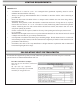
VENTING REQUIREMENTS: • • • • • • • HEIGHT & CLEARANCE: Vent system must terminate to the outside (Roof or side wall). DO NOT terminate the vent system in an attic or other enclosed area. DO NOT use 4” (10.2 cm) laundry-type wall caps. Use metal/aluminum vent only. Rigid metal/ aluminum vent is recommended. DO NOT use plastic vent. Always keep the duct clean to ensure proper airflow. Calculate the following figures before installation: 1. Distance from the floor to the ceiling 2.
VENTING REQUIREMENTS: IMPORTANT: • • • • • • • • A minimum of 6” round or 3-1/4 x 10” rectangular duct (purchased separately) must be used to maintain maximum airflow efficiency. Always use rigid type metal/aluminum ducts if available to maximize airflow when connecting to provided duct. Please use Duct Run Calculation below to compute total available duct run when using elbows, transitions and caps. ALWAYS, when possible, reduce the number or transitions and turns.
VENTING METHODS: • • This range hood is factory set for venting through the roof or wall. Vent work can terminate either through the roof or wall. To vent through a wall, a 90° elbow is needed. IMPORTANT: • • • • NEVER exhaust air or terminate duct work into spaces between walls, crawl spaces, ceiling, attics or garages. All exhaust must be ducted to the outside. Use metal/aluminum duct work only. Fasten all connections with sheet metal screws and tape all joints with certified aluminum or foil tape.
ELECTRICAL REQUIREMENTS: IMPORTANT: Observe all governing codes and ordinances. It is the customer’s responsibility to contact a qualified electrical installer. If codes permit and a separate ground wire is used, it is recommended that a qualified electrician determine that the ground path is adequate. A 120-Volt, 60 Hz, AC-only, fused electrical supply is required on a separate 15-amp circuit, fused on both sides of the line. DO NOT ground to a gas pipe.
PREPARATIONS: Advanced Preparations: • Be familiar with the controls of the range hood by reading through Range Hood Operations, Page 12. • Place the range hood on a flat, stable surface. Connect the range hood to a designated standard outlet (120-Volt, 60Hz, AC only) and turn on the range hood. Verify all operations of the range hood by referring to Range Hood Operations.
INSTALLATION: Installations ( refer to page 4 for parts): NOTE: Use threaded drywall anchors only when mounting the hood on sheet rock. Mounting the hood on wall studs or lumbars is highly recommended. For consumer safety reasons, mounting screws and anchors have not been supplied with this range hood. Different wall and cabinetry construction methods require speciÿc types of screws and wall anchors.
INSTALLATION: Step 3 : Attaching the unit under the kitchen cabinets • Mark or drill a small hole on the mounting position according to the space and dimensions cited on the following drawings. .• Install the hood under the cabinet using suitable screws to fix in position. • Attach the range hood under the kitchen cabinets and ducting to the top round 6" damper and exhaust outdoors. • The following drawings show the mounting dimensions of the 30" (750mm) width and 36" (900mm) width.
Lights and Power Settings: • When the power is on the LCD panel is lit, the light will turn off after 15 seconds of inactivity. • Press the LIGHT button once and light will go on; press again to shut off • The motor has 3 speed levels. Press the SPEED button once to start the motor at low speed, press again to move up to medium speed and once more to reach maximum speed. • You can stop the motor by pressing the ON/OFF button.
MEASUREMENTS AND DIAGRAMS: ATTENTION WARNING This range hood is 9 3/4" high (247 mm) - For electric cook top you need min. 33 3/4" (857 mm) clearance distance between bottom of cupboard and cook top; - For gaz cook top you need 39 3/4" (1010 mm) clearance.
TROUBLE SHOOTING: 1) If the range hood or halogen light does not operate after installation: • Check if the range hood has been plugged in, make sure that all power has been turned back ON,fused not blown and all electrical wiring are properly connected. 2) The range hood vibrates when the blower is on: • The range hood might not have been secured properly on to the ceiling or wall. 3) The blower or fan seems weak: • Check that the duct sized used is at least 6” or 3-1/4 x 10”.
RANGE HOOD ASSEMBLY: 15
SPECIFICATIONS: Body design Stainless steel Power rating 120V / 60Hz (USA & Canada standard) cULus Certified General input power 405W Motor input power 400W Ampere 3.4A Levels of speed control 3 levels Airflow 620 CFM Noise Level (60db)/(65db)/(70db) Number of Motor Single motor Fan Type Centrifugal squirrel cage Control Type Electronic LCD Control Filtration Type 2 x Thin baffle filters Illumination 2 x 2.
BLOWER ASSEMBLY: No. 1 Motor 2 Impeller 3 Blower Description No. Description ELECTRICAL ASSEMBLY: No. 1 2 3 4 5 No.
USE AND CARE INFORMATION: Operations: • Read and understand all instructions and warnings in this manual before operating the appliance. Save these instructions for future reference. • Always leave safety grills and filters in place. Without these components, operating fans could catch on to hair, fingers and loose clothing. • NEVER dispose cigarette ashes, ignitable substances, or any foreign objects into fans. • NEVER leave cooking unattended.
MODÈLE: Sous l'armoire 30" AN-1282 INSTRUCTIONS IMPORTANTE DE SÉCURITÉ Lisez attentivement l’information importante suivante concernant l’installation, la sécurité et l’entretien. Gardez des instruction pour référence future.
AVIS IMPORTANT SUR LA SÉCURITÉ VEUILLEZ LIRE ET CONSERVER CES INSTRUCTIONS LISEZ TOUTES LES INSTRUCTIONS AVANT D'INSTALLER ET DE FAIRE FONCTIONNER CET APPAREIL • L'installation dans ce manuel est conçue pour des installateurs, des techniciens d'entretien ou des personnes qualifiées avec des antécédents similaires au niveau de leurs qualifications.
AVIS IMPORTANT SUR LA SÉCURITÉ VEUILLEZ LIRE ET CONSERVER CES INSTRUCTIONS LISEZ TOUTES LES INSTRUCTIONS AVANT D'INSTALLER ET DE FAIRE FONCTIONNER CET APPAREIL AVERTISSEMENT : POUR RÉDUIRE LES RISQUES D'UN INCENDIE DE GRAISSE DANS LE HAUT DE LA HOTTE : a) Ne jamais laisser les surfaces de chauffage sans surveillance lorsque vous cuisez à température élevée. Les débordements par bouillonnement causent de la fumée et des éclaboussures de graisse qui peuvent prendre feu.
PIÈCES FOURNIES : Filtres à mince déflecteur (2 pcs) Obturateur du clapet 4
EXIGENCES DE VENTILATION : • • • • • • • HAUTEUR ET DÉGAGEMENT : Le système de ventilation doit de terminer à l'extérieur (Toit ou mur latéral). NE faites PAS terminer le système de ventilation dans un grenier ou autre endroit fermé. N'utilisez PAS de capuchons muraux de 4'' (10,2 cm) de type pour salle de lavage. Utilisez un évent en métal/aluminium seulement. Un évent rigide en métal/aluminium est recommandé. N'utilisez PAS un évent en plastique.
IMPORTANT: • • • • • • • • Un conduit circulaire minimum de 6” ou rectangulaire de 3-1/4 x 10” (acheté séparément) doit être utilisé pour maintenir l'efficacité maximale de la circulation d'air. Utilisez toujours des gaines de type rigide en métal/aluminium si disponible, pour maximiser la circulation d’air en connectant à la gaine fournie.
MÉTHODES DE VENTILATION : • • Cette hotte de cuisinière est réglée en usine pour ventiler à travers le toit ou mur. Le conduit de ventilation peut soit se terminer à travers le toit ou mur. Pour ventiler à travers un mur, un coude de 90° est nécessaire. IMPORTANT: • • • N’évacuez JAMAIS de l’air ou ne faites pas terminer le conduit de ventilation dans des espace entre les murs, vides sanitaires, plafonds, greniers ou garages. Toutes les évacuations doivent être menées par des conduits à l’extérieur.
EXIGENCE ÉLECTRIQUE : IMPORTANT: Observez tous les codes et ordonnances de règlementation. Il est la responsabilité du client de contacter un installateur électrique qualifié. Si les codes le permettent et qu'un fil de connexion à la terre est utilisé, il est recommandé qu’un électricien qualifié détermine que le chemin de connexion à la terre est adéquat.
PRÉPARATION : Préparations avancées : • Soyez familier avec les contrôles de la hotte en lisant soigneusement Fonctionnement de la hotte, Page 12. • Placez la hotte de cuisine sur une surface plate stable. Connectez la hotte de cuisinière à une prise de courant standard désignée (120-Volt, 60Hz, AC seulement) et mettez la hotte sous tension. Vérifiez tous les fonctionnements de la hottede cuisinière en vous référant au Fonctionnement de la Hotte de cuisinière.
INSTALLATION : Installations (se réferer à la Page 4 pour les pièces): NOTE: Utilisez des ancrages filetés pour cloison sèche seulement au fixant la hotte sur des panneaux en gyproc. Fixation la hotte sure des on poteaux muraux ou des travers est hautement recommandé Pour des raisons de sécurité pour le consommateur, le montage des vis et des fixations n’est pas fourni avec cette hotte de cuisine.
INSTALLATION : ÉWDSH 3: $WWDFKHU VXU OHV DUPRLUHV GH FXLVLQH • Marquer ou percer un petit trou sur la position de fixation selon les dimensions des dessins suivant. • Inserer les vis adequates prevues dans les trous • Accrocher la hotte sur les vis • Attacher la hotte sous les armoires et attacher le conduit de ventilation sur l'amortisseur circulaire 6" et faites le sortir à l'exterieur.
FONCTIONNEMENT DU PANNEAU DE COMMANDES : Réglages de lumières et d’alimentation : • Lorsque l’appareil est sous tension, le ACL éclairage est allumé, la lumière s'éteindra après 15 secondes d’attente. • Appuyez le bouton LUMIÈRES une fois encore et la lumière s’allumera, appuyez à nouveau pour éteindre. • Le moteur comprend 3 niveaux de vitesse.
MESURES ET DIAGRAMMES : WARNING ATTENTION This range hood is 9 3/4" high (247 mm) - For electric cook top you need min. 33 3/4" (857 mm) clearance distance between bottom of cupboard and cook top; - For gaz cook top you need 39 3/4" (1010 mm) clearance.
DÉPANNAGE : 1) Si la hotte de cuisinière ou ampoule halogène ne fonctionne pas après l'installation : • Vérifiez si la hotte de cuisine a été branchée et assurez-vous que toute l'alimentation a été remise sous tension, que les fusibles ne sont pas grillés et que tout le câblage électrique est adéquatement connecté. 2) La hotte de cuisinière vibre lorsque le ventilateur fonctionne : • La hotte de cuisinière peut ne pas avoir été fixée adéquatement sur le plafond ou le mur.
ASSEMBLAGE DE LA HOTTE DE CUISINIÈRE : 15
CARACTÉRISTIQUES TECHNIQUES : Conception du corps Acier inoxydable sans soudure/Feuille de métal Classement d'alimentation 120V/ 60Hz (É.U. et Canada standard) cULus certifiée Puissanceabsorbée générale 405W Puissance absorbée du moteur 400W Ampère 3.
ASSEMBLAGE DU SOUFFLEUR : No. Description 1 Moteur 2 Turbine 3 Ventilateur du moteur No. Description ASSEMBLAGE ÉLECTRIQUE : No. 1 2 3 4 5 Description Base de boîtier électrique Panneau de circuit Couverture électrique Condensateur Vis (ST3*10) No.
INFORMATION D'UTILISATION ET D'ENTRETIEN : Fonctionnement : • Lisez et comprenez toutes les instructions et tous les avertissements dans ce manuel avant de faire fonctionner l’appareil. Gardez ces instructions pour référence future. • Laissez toujours les grilles de sécurité et les filtres en place. Sans ces composantes, les souffleurs en opération pourraient accrocher les cheveux, les doigts et les vêtements amples.