UC PRO Turbo 30, 36 IMPORTANT SAFETY INSTRUCTIONS Carefully read the following important information regarding installation safety and maintenance. Keep these instructions for future reference.
Important Safety Notice Read all Instructions before Installing and operating this appliance • • • • • The installation in this manual is intended for qualified installers, service technicians or persons with similar qualified background. Installation and electrical wiring must be done by qualified professionals and in accordance with all applicable codes and standards, including fire-rated construction. DO NOT attempt to install this appliance yourself.
Important Safety Notice Read all Instructions before Installing and operating this appliance • • • Clean ventilating fan frequently. Always use appropriate cookware and utensils size. Always use cookware appropriate for the size of the surface element. To reduce the risk of injury to persons in the event of a stove top grease fire: • • • SMOTHER FLAMES with a close-fitting lid, cookie sheet, or metal tray, then turn OFF the burner. BECAREFUL TO PREVENT BURNS. NEVER PICK UP A FLAMING PAN—you may be burned.
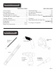
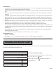
Table of Contents INSTALLATION Tools needed....................................................3 Parts supplied...................................................4 Venting requirements.......................................5 Mount heights & clearance...........................5-6 Calculating vent system length.......................6 Venting methods..............................................7 Electrical requirements....................................8 Preparation.........................................
Parts supplied: Under Cabinet Range Hood Qty: 4 PCS (For sheet rock only) Single-piece Chimney (Optional) Qty: 4 PCS Hood-mounting Bracket (Qty: 2PCS) Ducting Transition Qty: 8 PCS (Flat head) Optional for Single-piece Chimney Qty: 10 PCS (Round head) Qty: 8 PCS Baffle Filters Qty: 8 PCS Baffle Filter Spacer Qty: 8 PCS Grease Tunnel Page 4
Venting Requirements • • • • • • • Height & Clearance Vent system must terminate to the outside (roof or side wall). DO NOT terminate the vent system in an attic or other enclosed area. DO NOT use 4” (10.2 cm) laundry-type wall caps. Use metal/aluminum vent only. Rigid metal/ aluminum vent is recommended. DO NOT use plastic vent. Always keep the duct clean to ensure proper airflow. Calculate the following figures before installation: 1. Distance from the floor to the ceiling. 2.
IMPORTANT: • A minimum of 8” round (standard for this range hood) or 3-1/4 x 10” rectangular duct (purchased separately) must be used to maintain maximum airflow efficiency. • Always use rigid type metal/aluminum ducts if available to maximize airflow when connecting to provided duct. • Please use Duct Run Calculation below to compute total available duct run when using elbows, transitions and caps. • ALWAYS, when possible, reduce the number or transitions and turns.
Venting Methods • • This range hood is factory set for venting through the roof or wall. Vent work can terminate either through the roof or wall. To vent through a wall, a 90° elbow is needed. IMPORTANT: • • • • NEVER exhaust air or terminate duct work into spaces between walls, crawl spaces, ceiling, attics or garages. All exhaust must be ducted to the outside. Use metal/aluminum duct work only. Fasten all connections with sheet metal screws and tape all joints with certified Silver Tape or Duct Tape.
Electrical Requirements IMPORTANT: Observe all governing codes and ordinances. It is the customer’s responsibility: • To contact a qualified electrical installer. If codes permit and a separate ground wire is used, it is recommended that a qualified electrician determine that the ground path is adequate. A 120-Volt, 60 Hz, AC-only, fused electrical supply is required on a separate 15-amp circuit, fused on both sides of the line. DO NOT ground to a gas pipe.
Preparation Advanced Preparations: • Be familiar with the controls of the range hood by reading through Range Hood Operations, Page 12. • Place the range hood on a flat, stable surface. Connect the Excessive Weight range hood to a designated standard outlet (120-Volt, 60Hz, Require three or more person to move and AC only) and turn on the range hood. Verify all operations install this range hood.
Installation I t ll ti Installations (refer ( f tto P Page 4 ffor parts): 1. Measure the distance between stove top and the bottom of range hood. A distance of 27” to 30” is recommended*. *Due to different ceiling height configurations, recommended height may not be applicable. 1. You have two ways (A or B) to mount this range hood: A–1. Proceed if you would like to mount this range hood without using the hood-mounting bracket. A–2.
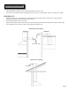
Installation (Continued) 5. 6. 7. 8. Store excess wires in the wiring box. OPTIONAL: If you purchased a single-piece chimney cover, attach it to the hood in this step. Drop oil tunnel into recess support near rear of hood. Refer to Figure 9. To install baffle filters and stainless spacer(s), refer to Baffle Filters and Stainless Steel Spacers on Page 18 for baffle filter and stainless spacer placement. Refer to Figure 10 for the following five steps: Angle baffle filter toward back of hood.
Range Hood Operations Control Panel Layout and Buttons Configurations: This range hood is equipped with six electronic controls, oversized powerful centrifugal squirrel cage motor with stainless steel baffle filters and spacers, two bright 3 W LED lights. The six electronic buttons control the intensity of the Lights, Speeds (Quiet, Low, Medium and High) and Power (On/Off). The Power Control (On/Off) offers startup, 3-minute delay or immediate power-off.
Range Hood Operations (Continued) Control Panel Layout and Buttons Configurations: • During this 3-minutes delay, changing speeds will not affect the countdown. Immediate Power-off • While the fans are in 3-minute power-off delay mode, press the Power Control (On/Off) button once to turn OFF the fans immediately. • When the fans are operating in normal mode (LED Speed Indicator not flashing), press the Power Control (On/Off) twice to turn OFF the fans.
Troubleshooting 1. If the range hood or LED light does not operate after installation: • • Check if the range hood has been plugged in, make sure that all power has been turned back ON, fused not blown and all electrical wiring are properly connected. Swap out light assembly to working ones to determine whether it is caused by defective bulbs. See Replacing the light bulbs on Page 23. 2.
Use and Care Information Operations: • • • • • Read and understand all instructions and warnings in this manual before operating the appliance. Save these instructions for future reference. Always leave safety grills and filters in place. Without these components, operating blowers could catch on to hair, fingers and loose clothing. NEVER dispose cigarette ashes, ignitable substances, or any foreign objects into blowers. NEVER leave cooking unattended.
Measurements and Diagrams • • All measurements in parenthesis are in millimeter. All inch measurements are converted from millimeters, thus inch measurements are estimated.
• • All measurements in parenthesis are in millimeter. All inch measurements are converted from millimeters, thus inch measurements are estimated.
• • All measurements in parenthesis are in millimeter. All inch measurements are converted from millimeters, thus inch measurements are estimated.
Baffle Filters and Stainless Steel Spacers: 30” Range Hood 36” Range Hood Circuit Diagram: Page 19
Range Hood Assembly: No. Description 1 Hood Casing 2 Ducting Transition 3 Screw 4 Blower Assembly 5 Oil Tunnel 6 Panel 7 Light Panel 8 Light 9 Screws No.
Blower Assembly: No. Description 4.1 Screw 4.2 Air Flow Grill 4.3 Left Locknut 4.4 Left Squirrel Cage No. 4.5 4.6 4.7 4.8 Description Motor Right Squirrel Cage Right Locknut Air Chamber Optional Single-Piece Chimney (Sold Separately): No. Description 3 Screws (3/16” x 3/8”) No.
Electrical Assembly: No. 21.1 21.2 21.3 21.4 21.5 21.6 21.7 Description Bolt Electrical Box Screws (3/16” x 3/8”) Processor Board Electrical Box Cover Electrical Box Base Screws (3/16” x 3/8”) No. 21.8 21.9 21.10 21.11 21.12 21.
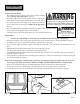
Maintenance SAFETY WARNING WARNING: N Never put your hand into area housing the fan while the fan is operating! For optimal operation, clean range hood and all baffle/spacer/filter/grease tunnel/oil container regularly. Regular care will help preserve the appearance of the range hood. Cleaning Exterior surfaces: • • • • • • Clean periodically with hot soapy water and clean cotton cloth. DO NOT use corrosive or abrasive detergent (e.g.
LIMITED PRODUCT WARRANTY Subject to the limitations, exclusions and disclaimers hereof, AMS warrants exclusively to the original purchaser (the “Purchaser”) of this Ancona Range hood product (the “Product”) that it shall be free from defects in material or workmanship (the “Limited Product Warranty”). The duration of the Limited Product Warranty is 12 months from the date of original purchase (the “Warranty Period”).