® Range Hood Slim SDR and Slim SDRW 30 inch User Manual & Installation Instructions IMPORTANT SAFETY INSTRUCTIONS Carefully read the important information regarding installation, safety and maintenance. Keep these instructions for future reference.
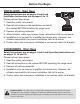
Before You Begin INSTALLERS - Start Here Safety Instructions are on pages 4 and 5 and Installation Instructions are on pages 8 to 14. Please perform these steps: 1. Read the safety instructions. 2. Read all instructions in the Installation section of this manual BEFORE installing the range hood. 3. Remove all packing materials. 4. When finished, make sure to leave these instructions with the consumer. 5. Installation is to be done by a qualified technician only.
Table of Contents Before You Begin................................................................................................................................ 2 Table of Contents............................................................................................................................... 3 Important Safety Information............................................................................................................. 4 Included Parts..............................................
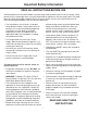
Important Safety Information READ ALL INSTRUCTIONS BEFORE USE Read and follow all instructions before using the range hood to prevent the risk of fire, electric shock, personal injury, or damage when using the range hood or appliances with the range hood. This guide does not cover all possible conditions that may occur. Always contact your service technician or manufacturer about problems that you do not understand.
Important Safety Information WARNING: TO REDUCE RISK OF A RANGE TOP GREASE FIRE: To reduce the risk of injury to persons in the event of a gas leaks: a) Never leave surface units unattended at high settings. Boilovers cause smoking and greasy spillovers that may ignite. Heat oils slowly on low or medium settings. • Extinguish any open flame. • DO NOT turn on the lights or any type of appliance. • Open all doors and windows to disperse the gas.
Included Parts Range Hood 2 Filters Vent/Damper Rubber Bushing 10 + 1 Damper Screws Cable tie Suction Cup (to remove GU10 lightbulb) Hardware Note: For safety reasons, range hood mounting screws and anchors will not be included due to the variation of cabinetry constructions and wall material. Please consult your installation specialist regarding the optimal type of mounting screws and wall anchors to suit your home’s construction.
Range Hood Dimensions 5c (1.9 m 6 in ./po m .6 65 in./ 10 (3 1/8 cm in./ po .) (19 ./po po. ) .) (25 .) 7/ po. (5 in./po.) cm 8 in in./ /po n. 8i ) 12.7 cm 48 (11. ( 1 3/4 in./po.) 8c . 25 16 c (6 5 m /16 m( .) /po in. 1 cm 4c 4.5 cm m 5c ( 10 30. 25. .) in./ 75 po. cm (29 1/ .) /po n. 2i ) 7.2 cm (2 .83 in./p o.) 25.5 cm ( 10 in./p o.
Installation STEP 1 Read the Safety Instructions • It is very important to read the safety instructions on pages 4 and 5. IMPORTANT: It is the installer’s responsibility to comply with installation clearances. STEP 2 Unpack Range Hood and Prepare Tools • Carefully unpack the range hood and parts. Make sure all parts are included as shown on page 6. • DO NOT remove the protective film covering the appliance until the installation is fully completed.
Installation STEP 5 Venting Installation Guidelines Height and Clearance (interior and exterior ventilation) 24 in. (610 mm) Min / 30 in. (762 mm) Max • The following steps are for exterior ventilation. IMPORTANT: • Vent system must terminate to the outside (roof or side wall). • DO NOT terminate the vent system in an attic or other enclosed area. • DO NOT use 4 in. (10.2 cm) laundry-type wall caps. • Use metal/aluminum vent only. A rigid metal/aluminum vent is recommended. • DO NOT use a plastic vent.
Installation IMPORTANT: • A minimum of 6 in. (15.2 cm) round or 3-1/4 x 10 in. (25.4 cm x 8.3 cm) rectangular duct (purchased separately) must be used to maintain maximum airflow efficiency. • Always use rigid type metal/aluminum ducts if available to maximize airflow when connecting to provided duct. • Please use Duct Run Calculation below to compute total available duct run when using elbows, transitions and caps. • ALWAYS, when possible, reduce the number or transitions and turns.
Installation • If performing new exterior installation, please follow Step 6 • If performing replacement installation or interior recirculation, please skip Step 6 and continue to Step 7 STEP 6 Create Exterior Ventilation (New Installation Only) • Choose one of the exterior venting methods shown on Page 10. • Create the exterior ventilation hole. • Insert exterior damper into exterior ventilation hole.
Installation STEP 8 Attaching Vent/Damper • When installing with internal recirculation function, unscrew the three screws from top plate of range hood. (See Fig #3) • Remove the steel panel from top of the range hood and replace with venting plate. (See Fig #4) • If choosing exterior venting option, depending on the exterior venting option chosen (See page 10), pop out the steel panel on either the top or rear of the range hood.
Installation • Secure all the leads inside the wiring compartment. • Secure the wiring compartment with a screw. • WARNING: ALL CONNECTORS MUST BE ENCLOSED IN THE WIRING COMPARTMENT. (See Fig #9) SAFETY WARNING: Risk of electrical shock. This range hood must be properly grounded. Make sure this is done by a qualified electrician in accordance with all applicable national and local electrical codes.
Installation STEP 12 Install Filters To install filters follow these four steps (See Figure #10): • Angle the filter into slots at the back of the hood. • Push the button on handle of the filter. • Release the handle once the filter fits into a resting position. • Repeat to install all filters.
Operation Low Speed Power Medium Speed Power Settings High Speed Light Lights Press the button once and the motor starts to operate at Low speed. u u v Press the button speed. and the motor will reach Medium w Press the button speed. the motor will reach High x Press the button to turn the fan off. Press the light button and off.
Maintenance Replacing the Light Bulbs This range hood uses halogen bulbs: 35 W 120V Type MR16 GU10. IMPORTANT: ALWAYS SWITCH OFF THE ELECTRICITY SUPPLY AT THE MAIN PANEL BEFORE CARRYING OUT ANY OPERATION ON THE APPLIANCE. u Make sure the electrical power to the range hood is turned off. Please note that the light bulbs may be hot . Allow enough time to let the light bulbs cool off before attempting to change them.
Range Hood Assembly 8 17 11 Number Part 16 1 Halogen Lamp 2 Lamp base 3 Lamp board 4 Filter 5 Safety Screen 6 Cage Plate 7 Propeller 8 Wires 9 Capacitor 10 Box Cover 11 Housing 12 Lamp guide line 13 M17 Motor 14 Propeller Cage 15 Strengthen Strip 16 Housing Cover 4 17 Outlet 3 18 Switch 18 15 10 14 9 13 7 6 5 2 12 1 Wiring Box — 17 —
Assembly Circuit Diagram Blower assembly Number 1 2 Electrical Assembly Number 1 2 — 18 — Part Propeller Cage Motor 3 Propeller 4 Cage Plate 5 Safety screen Part Capacitor Electrical box cover
Use and Care Information Operations • Read and understand all instructions and warnings in this manual before operating the appliance. Save these instructions for future reference. • Always leave safety grills and filters in place. Without these components, operating fans could catch on to hair, fingers and loose clothing. • NEVER dispose cigarette ashes, ignitable substances, or any foreign objects into fans. • NEVER leave cooking unattended.
Please register your product warranty by visiting the Ancona Home website. Canada & USA Phone: 1-800-350-4562 Fax: 800-350-8563 Email: service@anconahome.com Website: www.anconahome.com Ancona is in association with Mr Appliance for all after sales service calls. Please contact their service provider or visit their website: Phone: 1-888-998-2011 Website: www.mrappliance.com MAAN1290R-02 © 2019 Copyright of Ancona Home. All rights reserved.