MOEL: DEL: CHEF BUILT IN 28" & 34" IMPORTANT SAFETY INSTRUCTIONS Carefully read the following important information regarding installation safety and maintenance. Keep these instructions for future reference.
IMPORTANT SAFETY NOTICE READ AND SAVE THESE INSTRUCTIONS READ ALL INSTRUCTIONS BEFORE INSTALLING AND OPERATING THIS APPLIANCE ● The installation in this manual is intended for qualified installers, service technicians or persons with similar qualified background. Installation and electrical wiring must be done by qualified professionals and in accordance with all applicable codes and standards, including fire-rated construction.
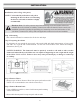
IMPORTANT SAFETY NOTICE READ AND SAVE THESE INSTRUCTIONS READ ALL INSTRUCTIONS BEFORE INSTALLING AND OPERATING THIS APPLIANCE WARNING: TO REDUCE RISK OF A RANGE TOP GREASE FIRE: a) Never leave surface units unattended at high settings. Boilovers cause smoking and greasy spillovers that may ignite. Heat oils slowly on low or medium settings. b) Always turn hood ON when cooking at high heat or when flambeing food (i.e. Crepes Suzette, Cherries Jubilee, Peppercorn Beef Flambé).
Hardware Note: For safety reasons, range hood mounting screws and anchors will not be included due to the variation of cabinetry constructions and wall material. Please consult your installation specialist regarding the optimal type of mounting screws and wall anchors to suit your home’s construction.
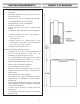
HEIGHT & CLEARANCE: VENTING REQUIREMENTS: • Vent system must terminate to the outside (Roof or side wall). • DO NOT terminate the vent system in an attic or other enclosed area. DO NOT use 4” (10.2 cm) laundry-type wall caps. • • • • • Use metal/aluminum vent only. Rigid metal/aluminum vent is recommended. DO NOT use plastic vent. Always keep the duct clean to ensure proper airflow. Calculate the following figures before installation: 1. Distance from the floor to the ceiling; Distance 2.
IMPORTANT: • • • • • • • • A minimum of 6” round or 3-1/4 x 10” rectangular duct (purchased separately) must be used to maintain maximum airflow efficiency. Always use rigid type metal/aluminum ducts if available to maximize airflow when connecting to provided duct. Please use Duct Run Calculation below to compute total available duct run when using elbows, transitions and caps. ALWAYS, when possible, reduce the number or transitions and turns.
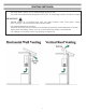
VENTING METHODS: • • This range hood is factory set for venting through the roof or wall. Vent work can terminate either through the roof or wall. To vent through a wall, a 90° elbow is needed. IMPORTANT: • • • • NEVER exhaust air or terminate duct work into spaces between walls, crawl spaces, ceiling, attics or garages. All exhaust must be ducted to the outside. Use metal/aluminum duct work only. Fasten all connections with sheet metal screws and tape all joints with certified aluminum or foil tape.
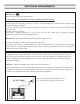
ELECTRICAL REQUIREMENTS: IMPORTANT: Observe all governing codes and ordinances. It is the customer’s responsibility to contact a qualified electrical installer. If codes permit and a separate ground wire is used, it is recommended that a qualified electrician determine that the ground path is adequate. A 120-Volt, 60 Hz, AC-only, fused electrical supply is required on a separate 15-amp circuit, fused on both sides of the line. DO NOT ground to a gas pipe.
PREPARATIONS: Advanced Preparations: • Be familiar with the controls of the range hood by reading through Range Hood Operations, Page 14. • Place the range hood on a flat, stable surface. Connect the range hood to a designated standard outlet (120-Volt, 60Hz, AC only) and turn on the range hood. Verify all operations of the range hood by referring to Range Hood Operations.
INSTALLATION: Installations (refer to Page 4 for parts): NOTE: Use threaded drywall anchors only when mounting the hood on sheet rock. Mounting the hood on wall studs or lumbars is highly recommended. Hardware Note: For safety reasons, range hood mounting screws and anchors will not be included due to the variation of cabinetry constructions and wall material. Please consult your installation specialist regarding the optimal type of mounting screws and wall anchors to suit your home’s construction.
INSTALLATION: Step 5: Remove Knock-Out Opening • From inside the power pack, remove the wiring cover by removing 2 retaining screws and set aside. Punch out the electrical knockout hole on top of the power pack. Install the wire clamp (included in parts bag). Fig#6 Fig#5 Fig#7 Step 6: Install Adapter/Damper • Using 4 no. 8 x 3/8' screws from parts bag, assemble the adapter/damper on the top of the power pack. To ensure proper opening of the dampers, remove shipping tape if present.
INSTALLATION: Step 7: Connect Wiring Fig#11 • Position the power pack below the installed custom hood. Insert the house wiring cable through the wire clamp previously installed in step 7. Tighten the wire clamp to secure the cable. • Using the provided wire connectors, connect power pack wires to power cable into wiring box • Connect wires as follow: BLACK to BLACK, WHITE to WHITE and GREEN or bare wire under ground screw. DO NOT FORGET TO CONNECT THE GROUND. Reinstall wiring cover.
INSTALLATION: Step 8: Reinstall Baffle Filter CAUTION: Remove plastic film covering filters before installing them. NOTE: Assemble the metal handles to the filters, using provided no. 8-32 x 1/4" screws, before installing them in the power pack. It is recommended to install side filters first and finish with center one(s). 1 Insert one end of the filter into the upper channel of the power pack. 2 Raise the other end towards the inside of power pack and insert in the grease drip rail of the power pack.
MEASUREMENTS AND DIAGRAMS: 13
CONTROL PANEL OPERATION: This range hood is equipped with six electronic controls, two stainless steel baffle filters, and two bright LED lights. The six electronic buttons control the intensity of the Lights, Speeds (Quiet, Low, Medium and High) and Power (On/Off). The Power Control (On/Off) offers startup, 3-minute delay or immediate power-off. The Light Control operates independently from the Power Control (On/Off) and is not affected by the delay shutoff.
TROUBLE SHOOTING: 1) If the range hood or LED light does not operate after installation: • Check if the range hood has been plugged in, make sure that all power has been turned back ON, fused not blown and all electrical wiring are properly connected. 2) The range hood vibrates when the blower is on: • The range hood might not have been secured properly on to the ceiling or wall. 3) The blower or fan seems weak: • Check that the duct sized used is at least 6”.
16 14 Adapter/Damper Adapter/Damper Round 16 17
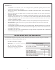
SPECIFICATIONS Body Design Power Rating General Input Power Motor Input Power Ampere Levels Of Speed Control Specifications: Stainless Steel 430 120V / 60Hz (USA & Canada standard) cULus 224 W 218 W 2.
BLOWER ASSEMBLY: No. 1 2 3 4 5 Description No. Motor Air Chamber Squirrel Cage Locknut Safety Screen ELECTRICAL ASSEMBLY: No. Description 1 Screws (3/16” x 3/8”) 2 Electrical Box Cover 3 Processor Board 4 Screws (3/16” x 3/8”) 5 Electrical Box Base No.
USE AND CARE INFORMATION: Operations: • Read and understand all instructions and warnings in this manual before operating the appliance. Save these instructions for future reference. • Always leave safety grills and filters in place. Without these components, operating fans could catch on to hair, fingers and loose clothing. • NEVER dispose cigarette ashes, ignitable substances, or any foreign objects into fans. • NEVER leave cooking unattended.