® Built-in Range Hood User Manual & Installation Instructions IMPORTANT SAFETY INSTRUCTIONS Carefully read the important information regarding installation, safety and maintenance. Keep these instructions for future reference.
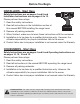
Before You Begin INSTALLERS - Start Here Safety Instructions are on pages 4 and 5 and Installation Instructions are on pages 8 to 13. Please perform these steps: 1. Read the safety instructions. 2. Read all instructions in the Installation section of this manual BEFORE installing the range hood. 3. Remove all packing materials. 4. When finished, make sure to leave these instructions with the consumer. 5. Installation is to be done by a qualified technician only.
Table of Contents Before You Begin................................................................................................................................ 2 Table of Contents............................................................................................................................... 3 Important Safety Information............................................................................................................. 4 Included Parts..............................................
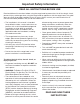
Important Safety Information READ ALL INSTRUCTIONS BEFORE USE Read and follow all instructions before using the range hood to prevent the risk of fire, electric shock, personal injury, or damage when using the range hood or appliances with the range hood. This guide does not cover all possible conditions that may occur. Always contact your service technician or manufacturer about problems that you do not understand.
Important Safety Information WARNING: TO REDUCE RISK OF A RANGE TOP GREASE FIRE: To reduce the risk of injury to persons in the event of a gas leaks: a) Never leave surface units unattended at high settings. Boilovers cause smoking and greasy spillovers that may ignite. Heat oils slowly on low or medium settings. • Extinguish any open flame. • DO NOT turn on the lights or any type of appliance. • Open all doors and windows to disperse the gas.
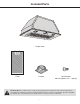
Included Parts Range Hood 1 Filter Damper Vent/Damper Mounting Screws (4 + 1 pieces) Hardware Note: For safety reasons, range hood mounting screws and anchors will not be included due to the variation of cabinetry constructions and wall material. Please consult your installation specialist regarding the optimal type of mounting screws and wall anchors to suit your home’s construction.
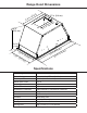
Range Hood Dimensions ) m 0c .8 11 (3 in. 3.7 in. (9.4 cm) m) n. 1i 6. 10 in. (25.4 cm) c 5.5 (1 0.4 in. (1 cm) 11 .6 10 .2 in. (29 in. .6 (26 cm 19 cm . 8 . (4 in ) n. 4i . 20 ) m 3c ) (5 m 2c ) Specifications Body Design Power Rating Total Input Power Motor Input Power Amperage Speed Control Levels Interference Protection Motors Control Filtration Illumination Fan Type Venting Size Stainless Steel 120 V / 60 Hz (cETLus Certified) 214 W (210 W + 2 x 2 W) 210 W 2.
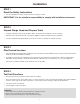
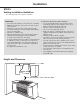
Installation STEP 1 Read the Safety Instructions • It is very important to read the safety instructions on pages 4 and 5. IMPORTANT: It is the installer’s responsibility to comply with installation clearances. STEP 2 Unpack Range Hood and Prepare Tools • Carefully unpack the range hood and parts. Make sure all parts are included as shown on page 6. • DO NOT remove the protective film covering the appliance until the installation is fully completed.
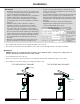
Installation STEP 5 Venting Installation Guidelines • The following steps are for exterior ventilation. IMPORTANT: • Vent system must terminate to the outside (roof or side wall). • DO NOT terminate the vent system in an attic or other enclosed area. • DO NOT use 4 in. (10.2 cm) laundry-type wall caps. • Use metal/aluminum vent only. A rigid metal/aluminum vent is recommended. • DO NOT use a plastic vent. • Always keep the duct clean to ensure proper airflow.
Installation IMPORTANT: • A minimum of 6 in. (15.3 cm) round or 3-1/4 x 10 in. (8.3 cm x 25.4 cm) rectangular duct (purchased separately) must be used to maintain maximum airflow efficiency. • Always use rigid type metal/aluminum ducts if available to maximize airflow when connecting to provided duct. • Please use Duct Run Calculation below to compute total available duct run when using elbows, transitions and caps. • ALWAYS, when possible, reduce the number or transitions and turns.
Installation STEP 6 Preparations NOTE: To avoid damage to your hood, prevent debris from entering the vent opening. • Determine and mark the centre line on the ceiling or wall where the range hood will be installed. • Make sure there is proper clearance within the ceiling or wall for exhaust vent. • Due to the weight and size of this unit, please make sure that the support system or framework being used is stable and secure in the ceiling or wall.
Installation STEP 9 Installing the Hood • Remove the filter, LED lights and the range hood cover. (See Fig #3) • Align range hood to the opening in the bottom of the cabinet and screw in with screws. (See Fig #4) Fig #3 Fig #4 STEP 10 Venting • Depending on the exterior venting chosen (See Page 10), either exit the ducting through the ceiling or wall. • Always use rigid type metal/aluminum duct tube (following the building codes in your area) to maximize airflow.
Installation IMPORTANT: • Observe all governing codes and ordinances. • It is the customer’s responsibility to contact a qualified electrical installer. • If codes permit and a separate ground wire is used, it is recommended that a qualified electrician determine that the ground path is adequate. A 120-Volt, 60 Hz, AC-only, fused electrical supply is required on a separate 15-amp circuit, fused on both sides of the line. • DO NOT ground to a gas pipe.
Operation Stop Low Speed Medium Speed Power Settings Press the button once and the motor starts to operate at Low speed. u v Press the button speed. and the motor will reach Medium w Press the button speed. the motor will reach High x Press the button to turn the fan off. Lights u Press the light button to turn lights on and off.
Troubleshooting Problem Possible Cause If the range hood or LED light does Check if the range hood has been plugged in, make sure that not operate after installation: all power has been turned back ON, fused not blown and all electrical wiring are properly connected. The range hood vibrates when the The range hood might not have been secured properly on to the blower is on: ceiling or wall. The blower or fan seems weak: Check that the duct sized used is at least 6 in. (15.3 cm) or 3 1/4 x 10 in. (8.3 x 25.
Maintenance Replacing the Light Pucks IMPORTANT: ALWAYS SWITCH OFF THE ELECTRICITY SUPPLY AT THE MAIN PANEL BEFORE CARRYING OUT ANY OPERATION ON THE APPLIANCE. u Make sure the range hood is unplugged or turn OFF breaker. v Remove filter. Reach into interior of range hood until touching both lateral clips located on the side of the puck light. Gently squeeze and push down until puck pops out from its location, pull out the LED puck and unplug it.
Range Hood Assembly Number Part 1 Power cord 2 Round duct or valve (Exhaust) 3 Housing assembly 4 5 6 Blower assembly (includes motor) 7 — 17 — 8 Electronic box 9 PCB 10 Capacitor 11 Cover of electronic box 12 Cover of switch box 13 Switch board 14 Bracket of switch 15 Panel 16 Cover of terminal 17 Terminal box 18 LED puck lights 19 Decorative Filter (1 piece) 20 Screw bag
Assembly Circuit Diagram AC 120V 60Hz M Blower Assembly Number Part 1 Grid 2 Motor 3 Impeller 4 Blower 5 Wind drum inlet Main PCB Push Button L N E Capacitor u v w x y Electrical Assembly u u v v w w x x Number Part 1 Electronic box 2 PCB 3 Capacitor 4 Cover of electronic box — 18 —
Use and Care Information Operations • Read and understand all instructions and warnings in this manual before operating the appliance. Save these instructions for future reference. • Always leave safety grills and filters in place. Without these components, operating fans could catch on to hair, fingers and loose clothing. • NEVER dispose cigarette ashes, ignitable substances, or any foreign objects into fans. • NEVER leave cooking unattended.
Please register your product warranty by visiting the Ancona Home website. Canada & USA Phone: 1-888-686-0778 Fax: 800-350-8563 Email: service@anconahome.com Website: www.anconahome.com Ancona is in association with Mr Appliance for all after sales service calls. Please contact their service provider or visit their website: Phone: 1-888-998-2011 Website: www.mrappliance.com MAAN1314-01 © 2019 Copyright of Ancona Home. All rights reserved.