® IGCB636 Range Hood User Manual & Installation Instructions IMPORTANT SAFETY INSTRUCTIONS Carefully read the important information regarding installation, safety and maintenance. Keep these instructions for future reference.
Before You Begin INSTALLERS - Start Here Safety Instructions are on pages 4 and 5 and Installation Instructions are on pages 9 to 15. Please perform these steps: 1. Read the safety instructions. 2. Read all instructions in the Installation section of this manual BEFORE installing the range hood. 3. Remove all packing materials. 4. When finished, make sure to leave these instructions with the consumer. 5. Installation is to be done by a qualified technician only.
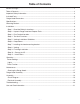
Table of Contents Before You Begin................................................................................................................................ 2 Table of Contents............................................................................................................................... 3 Important Safety Information............................................................................................................. 4 Included Parts..............................................
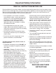
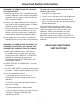
Important Safety Information READ ALL INSTRUCTIONS BEFORE USE Read and follow all instructions before using the range hood to prevent the risk of fire, electric shock, personal injury, or damage when using the range hood or appliances with the range hood. This guide does not cover all possible conditions that may occur. Always contact your service technician or manufacturer about problems that you do not understand.
Important Safety Information WARNING: TO REDUCE RISK OF A RANGE TOP GREASE FIRE: To reduce the risk of injury to persons in the event of a gas leaks: a) Never leave surface units unattended at high settings. Boilovers cause smoking and greasy spillovers that may ignite. Heat oils slowly on low or medium settings. • Extinguish any open flame. • DO NOT turn on the lights or any type of appliance. • Open all doors and windows to disperse the gas.
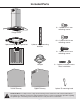
Included Parts 8 + 1 pieces ST4*8 mm mounting screws Range Hood 40 + 1 pieces M4*10 mm mounting screws 1 piece ceiling mounting bracket 8 pieces angle mounting brackets 4 + 1 pieces M4*22 mm mounting screws 2 pieces filter Damper 4 + 1 pieces washers/screws Glass installation Lower Chimney Upper Chimney 1 piece `S` mounting hook Hardware Note: For safety reasons, range hood mounting screws and anchors will not be included due to the variation of cabinetry constructions and wall material.
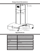
Range Hood Dimensions 65.4 - 124 cm (25.7 - 48.8 in.) 28.6 cm (11.25 in.) 28.6 cm (11.25 in.) 7.9 cm (3.1 in.) 57 cm (22.4 in.) 42.1 cm (16.5 in.) 89.5 cm (35.2 in.) 60 cm (23.6 in.) Specifications Body Design Stainless Steel Power Rating 120 V / 60 Hz (cETLus Certified) Total Input Power 376 W (365 W + 4 x 2.55 W) Motor Input Power 365 W Total Amps 3.
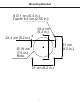
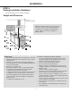
Mounting Bracket 8 Ø 1 cm (0.4 in.) Depth 6.5 cm (2.55 in.) 23.4 cm (9.2 in.) 23.4 cm (9.2 in.) 21 cm (8.2 in.) Ø 19 cm (7.5 in.) Hole 21 cm (8.2 in.
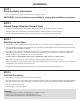
Installation STEP 1 Read the Safety Instructions • It is very important to read the safety instructions on pages 4 and 5. IMPORTANT: It is the installer’s responsibility to comply with installation clearances. STEP 2 Unpack Range Hood and Prepare Tools • Carefully unpack the range hood and parts. Make sure all parts are included as shown on page 6. • DO NOT remove the protective film covering the appliance until the installation is fully completed.
Installation STEP 5 Venting Installation Guidelines • The following steps are for exterior ventilation. Height and Clearance 114.8 in. (2.9 m) 30 in. (76.2 cm) Maximum ceiling clearance 114.8 in. (2.9 m) at 30 in. (76.2 cm) hood mounting height above countertop or stove (May vary with different model). Chimney extensions available for higher ceiling. 36 in. (91.4 cm) IMPORTANT: • Vent system must terminate to the outside (roof or side wall).
Installation IMPORTANT: • A minimum of 6 in. (15.3 cm) round or 3-1/4 x 10 in. (25.4 cm x 8.3 cm) rectangular duct must be used to maintain maximum airflow efficiency. • Always use rigid type metal/aluminum ducts if available to maximize airflow when connecting to provided duct. • Please use Duct Run Calculation below to compute total available duct run when using elbows, transitions and caps. • ALWAYS, when possible, reduce the number or transitions and turns.
Installation STEP 6 Preparations NOTE: To avoid damage to your hood, prevent debris from entering the vent opening. NOTE: Use threaded drywall anchors only when mounting the hood on sheet rock. Mounting the hood on wall studs or lumbers is highly recommended. • Determine and mark the centre line on the ceiling where the range hood will be installed. A distance of 24 inches to 30 inches from the stove top is recommended, with a minimum of 30 inches for gas stove tops.
Installation • Fix upper chimney on hanging scaffold. • Place lower chimney over upper chimney at proper position. • Insert hook into bracket to hold lower chimney temporarily. See Fig. #3. 4 - ST 4 x 8 Upper chimney Lower chimney Hook Fig. #3 Expandable pipe STEP 8 Venting • Fix air outlet onto the vent of hood’s body, connect expandable pipe to air outlet. See Fig. #4. Air outlet Fig.
Installation STEP 9 Finishing Installation Note: To avoid personal injury and/or damage to the range hood, this installation step requires three people. • Use 4 pieces M4*22mm mounting screws with washers to attach the glass into the hood. See Fig. #5. • Extend the hose from hanging scaffold, and fix hood’s body on bracket. See Fig. #6. • Detach the hook, move lower chimney downward until reaching hood’s body. Make sure not to strike glass. See Fig. #7. Fig. #5 Fig. #6 Fig.
Installation IMPORTANT: • Observe all governing codes and ordinances. • It is the customer’s responsibility to contact a qualified electrical installer. • If codes permit and a separate ground wire is used, it is recommended that a qualified electrician determine that the ground path is adequate. A 120-Volt, 60 Hz, AC-only, fused electrical supply is required on a separate 15-amp circuit, fused on both sides of the line. • DO NOT ground to a gas pipe.
Operation 15 minute delay On / Speed Up Off / Slow down LCD Power settings Light Timer Function u Press the button once and the motor starts to operate at Low speed. The control module provides the option to run the motor for a predetermined time period in order to evacuate remaining vapors from the kitchen. v Press the button again and the motor will reach Medium speed. u w Press the button once more and the motor will reach High speed Press the button while the motor is running.
Maintenance Cleaning the Range Hood Be sure electrical power is off and all surfaces are cool before cleaning or servicing any part of the hood. Proper maintenance of the Range Hood will ensure proper performance of the unit. Use a warm detergent solution. Grease filters are dishwasher safe. Stainless steel is one of the easiest materials to keep clean. Occasional care will help preserve its appearance. Cleaning tips: • Hot water with soap or detergent is all that is usually required.
Range Hood Assembly Number Part — 18 — 1 Stainless steel baffle filter 2 Blower assembly 3 Touch switch board 4 Touch switch 5 6 Touch switch box bracket Switch guide wire 7 Lamp guide wire 8 Lamp guide wire 9 LED puck lights 10 Decorative strip 11 Electrical box base 12 PCB 13 LED puck lights driver 14 3 holes tension disc 15 2 holes tension disc 16 Electrical box cover 17 Plug 18 Tempered glass 19 Lower chimney 20 Upper chimney 21 Hanging bracket 22 Hanging scaff
100.
Troubleshooting Problem Possible Cause If the range hood or LED light Check if the range hood has been plugged in, make sure that all power does not operate after installation: has been turned back ON, fused not blown and all electrical wiring are properly connected. The range hood vibrates when the The range hood might not have been secured properly on to the ceiling. blower is on: The blower or fan seems weak: Check that the duct sized used is at least 6 in. (15.3 cm) or 3 1/4 x 10 in. (25.4 x 8.3 cm).
Use and Care Information Operations • Read and understand all instructions and warnings in this manual before operating the appliance. Save these instructions for future reference. • Always leave safety grills and filters in place. Without these components, operating fans could catch on to hair, fingers and loose clothing. • NEVER dispose cigarette ashes, ignitable substances, or any foreign objects into fans. • NEVER leave cooking unattended.
Please register your product warranty by visiting the Ancona Home website. Canada & USA Phone: 1-888-686-0778 Fax: 800-350-8563 Email: service@anconahome.com Website: www.anconahome.com Ancona is in association with Mr Appliance for all after sales service calls. Please contact their service provider or visit their website: Phone: 888-998-2011 Website: www.mrappliance.com MAAN1406-01 © 2018 Copyright of Ancona Home. All rights reserved.