® Range Hood Tornado Island 48” User Manual & Installation Instructions IMPORTANT SAFETY INSTRUCTIONS Carefully read the important information regarding installation, safety and maintenance. Keep these instructions for future reference.
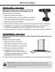
Before You Begin INSTALLERS - Start Here Safety Instructions are on pages 4 and 5 and Installation Instructions are on pages 9 to 15. Please perform these steps: 1. Read the safety instructions. 2. Read all instructions in the Installation section of this manual BEFORE installing the range hood. 3. Remove all packing materials. 4. When finished, make sure to leave these instructions with the consumer. 5. Installation is to be done by a qualified technician only.
Table of Contents Before You Begin................................................................................................................................ 2 Table of Contents............................................................................................................................... 3 Important Safety Information............................................................................................................. 4 Included Parts..............................................
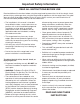
Important Safety Information READ ALL INSTRUCTIONS BEFORE USE Read and follow all instructions before using the range hood to prevent the risk of fire, electric shock, personal injury, or damage when using the range hood or appliances with the range hood. This guide does not cover all possible conditions that may occur. Always contact your service technician or manufacturer about problems that you do not understand.
Important Safety Information WARNING: TO REDUCE RISK OF A RANGE TOP GREASE FIRE: To reduce the risk of injury to persons in the event of a gas leaks: a) Never leave surface units unattended at high settings. Boilovers cause smoking and greasy spillovers that may ignite. Heat oils slowly on low or medium settings. • Extinguish any open flame. • DO NOT turn on the lights or any type of appliance. • Open all doors and windows to disperse the gas.
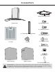
Included Parts Ceiling mounting bracket 8 x Mounting Screws Range Hood 42 x Mounting Screws 8 x Telescopic Ceiling Bracket 12 x Mounting Screws 2 x Filters Damper 8 x Explode screws 12 x drywall anchors 26 x Nuts 26 x Washers Lower Chimney Upper Chimney `S` mounting hook (1 pcs) Hardware Note: For safety reasons, range hood mounting screws and anchors will not be included due to the variation of cabinetry constructions and wall material.
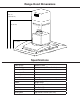
Range Hood Dimensions 40.5”- 46” (1030-1170 mm) 11.2” 26” (665 mm) (285 mm) 10.6” (270 mm) 6” (150 mm) 3.5” (90 mm) 16.5” 23.6” (600 (420 ” 24.44 mm) (570 ” 47.24 mm) mm) (1200 mm) Specifications Body Design Power Rating Stainless Steel 120 V / 60 Hz (cETLus Certified) Total Input Power 410 W Motor Input Power 400 W Total Amps 3.
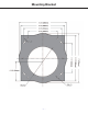
Mounting Bracket —8—
Installation STEP 1 Read the Safety Instructions • It is very important to read the safety instructions on pages 4 and 5. IMPORTANT: It is the installer’s responsibility to comply with installation clearances. STEP 2 Unpack Range Hood and Prepare Tools • Carefully unpack the range hood and parts. Make sure all parts are included as shown on page 6. • DO NOT remove the protective film covering the appliance until the installation is fully completed.
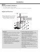
Installation STEP 5 Venting Installation Guidelines • The following steps are for exterior ventilation. • If you require a ductless installation, please visit anconahome.com to purchase a recirculation kit. Height and Clearance Maximum ceiling clearance 114” at 30” hood mounting height above countertop or stove (May vary with different model). Chimney extensions available for higher ceiling 24” (610 mm) Min. 30” (610 mm) Max. IMPORTANT: • Vent system must terminate to the outside (roof or side wall).
Installation IMPORTANT: • A minimum of 6” round or 3-1/4 x 10” rectangular duct (purchased separately) must be used to maintain maximum airflow efficiency. • Always use rigid type metal/aluminum ducts if available to maximize airflow when connecting to provided duct. • Please use Duct Run Calculation below to compute total available duct run when using elbows, transitions and caps. • ALWAYS, when possible, reduce the number or transitions and turns.
Installation STEP 6 Measuring • Measure the distance between stove top and the bottom of the range hood. A distance of 24” to 30” is recommended with a minimum of 30” for gas stove tops. • To reach 9ft ceiling make sure hood is installed at 30” from cooking surface. • If you require longer chimney flue to reach your ceiling please visit anconahome.com STEP 7 Installing the Hood Mounting bracket • Determine and mark the center line on the ceiling where the range hood will be installed.
Installation STEP 8 Venting • Fix the damper flap into the damper hole on top of the range hood motor box. (See Fig. #3) • Let the ducting pipe go inside through the hole from the ceiling. (See Fig. #4) • Measure the length of 6`` round metal duct required from the dampler / duct connector to the ductwork rough-in in the ceiling. Connect the duct to the damper / duct connector and seal with duct tape.
Installation STEP 10 Finishing Installation Note: To avoid personal injury and/or damage to the range hood, this installation step requires three people. • Slide the inner chimney up to the ceiling and attach it to the ceiling bracket using the screws. (See Fig. #7) • Remove the protective coating from the hood body and outer chimney.
Installation IMPORTANT: • Observe all governing codes and ordinances. • It is the customer’s responsibility to contact a qualified electrical installer. • If codes permit and a separate ground wire is used, it is recommended that a qualified electrician determine that the ground path is adequate. A 120-Volt, 60 Hz, AC-only, fused electrical supply is required on a separate 15-amp circuit, fused on both sides of the line. • The range hood must be connected with copper wire/plug only.
Operation Increase Decrease Timer Speed Speed Power Settings Light Timer Function Press the button + once and the motor starts to operate at Low speed. u u v Press the button + again and the motor will reach Medium speed. w Press the button + once more and the motor will reach High speed. x Press the button - to lower speeds in succession until the motor stops working (power off).
Range Hood Assembly — 17 — Number 1 2 Part Mounting plate Upper chimney 3 Mounting angle 4 Lower chimney 5 Duct tube (not included) 6 PCB box 7 Capacitor 8 Transformer 9 10 Connector Base of plastic box 11 Air outlet 12 13 Housing Power cord 14 Grill 15 Blower 16 Wheel 17 Motor 18 Glass 19 Switch box 20 Push button 21 Switch panel 22 Lights 23 Screws 24 Filter
Assembly Circuit Diagram Blower Assembly Number 1 2 Part Motor Impeller 3 Blower Electrical Assembly Number 1 2 Part Electrical Box Base PCB 3 Electrical Cover 4 Capacitor 5 Screw (ST3*10) 6 Screw (ST3*6) — 18 —
Use and Care Information Operations • Read and understand all instructions and warnings in this manual before operating the appliance. Save these instructions for future reference. • Always leave safety grills and filters in place. Without these components, operating fans could catch on to hair, fingers and loose clothing. • NEVER dispose cigarette ashes, ignitable substances, or any foreign objects into fans. • NEVER leave cooking unattended.
Please register your product warranty by visiting the Ancona Home website. Canada & USA Phone: 888-686-0778 Fax: 800-350-8563 Email: service@anconahome.com Website: www.anconahome.com Ancona is in association with Mr Appliance for all after sales service calls. Please contact their service provider or visit their website: Phone: 888-998-2011 Website: www.mrappliance.com MAAN1448-01 © 2016 Copyright of Ancona Home. All rights reserved.