® Range Hood WPB630 and WPB636 User Manual & Installation Instructions IMPORTANT SAFETY INSTRUCTIONS Carefully read the important information regarding installation, safety and maintenance. Keep these instructions for future reference.
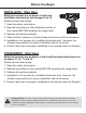
Before You Begin INSTALLERS - Start Here Safety Instructions are on pages 4 and 5 and Installation Instructions are on pages 9 to 15. Please perform these steps: 1. Read the safety instructions. 2. Read all instructions in the Installation section of this manual BEFORE installing the range hood. 3. Remove all packing materials. 4. When finished, make sure to leave these instructions with the consumer. 5. Installation is to be done by a qualified technician only.
Table of Contents Before You Begin................................................................................................................................ 2 Table of Contents............................................................................................................................... 3 Important Safety Information............................................................................................................. 4 Included Parts..............................................
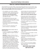
Important Safety Information READ ALL INSTRUCTIONS BEFORE USE Read and follow all instructions before using the range hood to prevent the risk of fire, electric shock, personal injury, or damage when using the range hood or appliances with the range hood. This guide does not cover all possible conditions that may occur. Always contact your service technician or manufacturer about problems that you do not understand.
Important Safety Information WARNING: TO REDUCE RISK OF A RANGE TOP GREASE FIRE: To reduce the risk of injury to persons in the event of a gas leaks: a) Never leave surface units unattended at high settings. Boilovers cause smoking and greasy spillovers that may ignite. Heat oils slowly on low or medium settings. • Extinguish any open flame. • DO NOT turn on the lights or any type of appliance. • Open all doors and windows to disperse the gas.
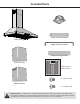
Included Parts Vent/Damper Lower Chimney Bracket Main Housing Upper Chimney Bracket Hood Mounting Bracket Lower Chimney 2 Filters (30 in.) 3 Filters (36 in.) 4 + 1 Screws (C) Upper Chimney 4 + 1 Screws (D) Hardware Note: For safety reasons, range hood mounting screws and anchors will not be included due to the variation of cabinetry constructions and wall material.
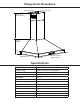
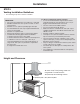
Range Hood Dimensions 22.1 cm (8.7 in.) 17.1 cm (6.7 in.) 40 - 78 cm (15.75 - 30.7 in.) 27 cm (10.6 in.) 5 cm (1.9 in.) 75 cm (29.5 in.) / 90 cm (35.4 in.) 50 cm (19.6 in.) Specifications Body Design Power Rating Total Input Power Motor Input Power Amperage Speed Control Levels Interference Protection Motors Control Filtration Illumination Fan Type Venting Size Stainless Steel 120 V / 60 Hz (cETLus Certified) 371 W (365 W + 2 x 2.55 W) 365 W 3.
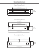
Mounting Brackets Upper Chimney Bracket 5 1/8” (13 cm) 1 3/8” (3.5 cm) 8 21/32 (22 cm) Lower Chimney Bracket 7 7/8” (20 cm) 5 1/8” (13 cm) 1 3/8” (3.5 cm) 8 5/8” (21.
Installation STEP 1 Read the Safety Instructions • It is very important to read the safety instructions on pages 4 and 5. IMPORTANT: It is the installer’s responsibility to comply with installation clearances. STEP 2 Unpack Range Hood and Prepare Tools • Carefully unpack the range hood and parts. Make sure all parts are included as shown on page 6. • DO NOT remove the protective film covering the appliance until the installation is fully completed.
Installation STEP 5 Venting Installation Guidelines • The following steps are for exterior ventilation. IMPORTANT: • Vent system must terminate to the outside (roof or side wall). • DO NOT terminate the vent system in an attic or other enclosed area. • DO NOT use 4 in. (10.2 cm) laundry-type wall caps. • Use metal/aluminum vent only. A rigid metal/aluminum vent is recommended. • DO NOT use a plastic vent. • Always keep the duct clean to ensure proper airflow.
Installation IMPORTANT: • A minimum of 6 in. (15.3 cm) round or 3-1/4 x 10 in. (25.4 cm x 8.3 cm) rectangular duct (purchased separately) must be used to maintain maximum airflow efficiency. • Always use rigid type metal/aluminum ducts if available to maximize airflow when connecting to provided duct. • Please use Duct Run Calculation below to compute total available duct run when using elbows, transitions and caps. • ALWAYS, when possible, reduce the number or transitions and turns.
Installation STEP 6 Preparations NOTE: To avoid damage to your hood, prevent debris from entering the vent opening. • Determine and mark the center line on the ceiling or wall where the range hood will be installed. • Make sure there is proper clearance within the ceiling or wall for exhaust vent. • Due to the weight and size of this unit, please make sure that the support system or framework being used is stable and secure in the ceiling or wall.
Installation STEP 9 Venting • Fix the damper on the top vent of hood with 4 screws (C). (See Figure #2) • If ventilation system is equipped with an external air duct with a different diameter, apply a reduction fitting. However, for maximum performance and safety, a 6 in. round ducting is recommended. Fig #2 STEP 10 Mount Range Hood onto Wall • Hang the range hood on the hooks of the hood mounting bracket. (See Figure #3) • Screw the range hood to the wall.
Installation • Hook lower chimney bracket to lower chimney. (See Figure #5) • Screw lower mounting bracket onto wall. • Screw the upper chimney to the upper mounting bracket (Screw D). (See Figure #6) STEP 13 Connect to AC • Fig #5 Connect AC plug into a grounded AC outlet having 120V, 60Hz. Place the outlet at a maximum distance of 33-1/2 in. (851 mm) from where the cord exits on the hood.
Installation STEP 14 Install Filters To install filters follow the steps below (See Figure #7): • Angle the filter into slots at the back of the hood. • Push the button on handle of the filter. • Release the handle once the filter fits into a resting position. • Repeat to install all filters.
Operation 15 minute delay On / Speed Up Off / Slow down LCD Power settings Light Timer Function u Press the button once and the motor starts to operate at Low speed. The control module provides the option to run the motor for a predetermined time period in order to evacuate remaining vapors from the kitchen. v Press the button again and the motor will reach Medium speed. u w Press the button once more and the motor will reach High speed Press the button while the motor is running.
Range Hood Assembly 22 Number 21 20 19 17 18 15 16 14 13 12 23 24 11 10 9 8 6 5 4 3 7 2 1 — 17 — Part 1 Front panel 2 Baffle filter (2 or 3 pcs) 3 Touch switch board 4 Touch switch box bracket 5 PCB of Touch switch 6 Touch switch box 7 LED puck light 8 Stainless steel frame 9 Blower assembly bracket 10 Blower assembly 11 Electrical box cover 12 PCB of Touch switch 13 Electrical box base 14 Bracket of electrical box 15 Rear board 16 Body assembly 17 Top tray 18
100.
Use and Care Information Operations • Read and understand all instructions and warnings in this manual before operating the appliance. Save these instructions for future reference. • Always leave safety grills and filters in place. Without these components, operating fans could catch on to hair, fingers and loose clothing. • NEVER dispose cigarette ashes, ignitable substances, or any foreign objects into fans. • NEVER leave cooking unattended.
Please register your product warranty by visiting the Ancona Home website. Canada & USA Phone: 1-888-686-0778 Fax: 800-350-8563 Email: service@anconahome.com Website: www.anconahome.com Ancona is in association with Mr Appliance for all after sales service calls. Please contact their service provider or visit their website: Phone: 888-998-2011 Website: www.mrappliance.com MAAN1524-01 © 2018 Copyright of Ancona Home. All rights reserved.