
Installation Guide

STEP 6
Install Anti-Tip Bracket
To reduce the risk of tipping of the range, the range must be
securedtotheoorwithaproperlyinstalledAnti-TipBracket
(included).
Failure to install the Anti-Tip Bracket will allow the range
to tip over if excessive weight is placed on an open door
or if a child climbs upon it. Serious injury might result from
spilled hot liquids or from the range itself. If range is ever
moved to a different location, the Anti-Tip Bracket must be
re-installed.
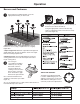
u
Contact a qualified floorcoveringinstaller
for the procedure of drilling mounting
holes through your typeoffloorcovering.
v
w
The Anti-Tip Bracket is to be installed
to secure
the range to thefloor, follow these stepsbefore
movingtherange into final operating position.
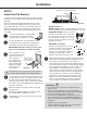
x
Place the bracket on the
floor with the back edge
against the rear wall.
If the range does
not reach the rear
wall, align the back
edge of the bracket
with the rear panel
of the range in its
final location.
y
If bracket does not touch the rear wall, you MUST
screw bracket to FLOOR as described in Step 6.
U
After installing the bracket, slide the range into its final
location. The rear leveling leg must be fully inserted
into the ANTI-TIP bracket as shown in Step 3. To
check if the bracket is installed and engaged properly,
look underneath the range to see that the rear leveling
leg is engaged in the bracket. On some models, the
storage drawer or kick panel can be removed for
easier inspection. If visual inspection is not possible,
slide the range forward, confirm the anti-tip bracket is
securely attached to the floor or wall, and slide the
range back so the leveling leg is under the anti-tip
bracket. If the range is pulled from the wall for any
reason, always repeat this procedure to verify the
range is properly secured by the anti-tip bracket.
engaged in the bracket. On
some
models, the storage drawer
or kick panel can be
pulled from the
wall for any reason, always
repeat this procedure to
verify the
range is properly secured by
the anti-tip bracket.
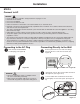
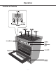
A. ¼" drive ratchet
B. Rear leveling leg
C. Wrench or pliers
D. Front leveling leg
A. Rear leveling leg
B. Front leveling leg
C. Wrench or pliers
A
B
C
D
A
B
C
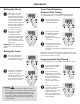
WARNING
Tip Over Hazard
A child or adult can tip the range and be killed.
Connect anti-tip bracket to rear range foot.
A. ¼" drive ratchet
B. Rear leveling leg
C. Wrench or pliers
D. Front leveling leg
A. Rear leveling leg
B. Front leveling leg
C. Wrench or pliers
A
B
C
D
A
B
C
WARNING
Tip Over Hazard
A child or adult can tip the range and be killed.
Connect anti-tip bracket to rear range foot.
A. ¼" drive ratchet
B. Rear leveling leg
C. Wrench or pliers
D. Front leveling leg
A. Rear leveling leg
B. Front leveling leg
C. Wrench or pliers
A
B
C
D
A
B
C
WARNING
Tip Over Hazard
A child or adult can tip the range and be killed.
Connect anti-tip bracket to rear range foot.
WARNINGS:
• PleasemakesuretoreadALLsafetyprecautionson
pages 4 to 10.
• Usetwoormorepeopletomoveandinstallrange.
•
Tip-over Hazard, a child or adult can tip the range and be killed.
•
Connect anti-tip bracket to rear range foot.
•
Reconnect the anti-tip bracket, if the range is moved.
•
The anti-tip bracket must be PROPERLY INSTALLED
and the rear leveling leg must be FULLY ENGAGED into
the bracket.
•
Failure to follow these instructions can result in death
or serious burns to children and adults.
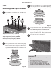
Installation
Figure 21
Figure 22
IMPORTANT: Determine the final location of the
range before attempting to install the bracket.
Rear Wall
Loc B
Loc C
Loc A
Adjacent cabinet
or final location of
range side panel
Position the side of the bracket against either the left
or right cabinet. If there is no adjacent cabinet, align
the edge of the bracket with the side panel of the
range in its final location. If the countertop overhangs
the cabinet, offset the bracket from the cabinet by the
amount of overhang.
Mark the location for the pair of holes to be used
(see Figure 21).
NOTE: For FLOOR installation use either Loc A or
B. For REAR WALL installation use Loc C.
The bracket must be screwed to either the FLOOR
or REAR WALL.
Screw must enter
wood or concrete
Attachment to Floor or Rear Wall
Wall Sill Plate
Screw must enter wood
Bracket
FLOOR Installation:
WOOD FLOOR: Use the screws provided to secure the
bracket using the pair of marked holes (either Loc A or B).
CONCRETE FLOOR: Using a concrete
bit, drill a 5/32” pilot hole 2” deep into
the concrete at the center of each of
the marked holes (either Loc A or B).
Use the screws provided to secure the
bracket into the floor.
REAR WALL Installation:
Use the 2 screws provided to secure
the bracket using the pair of marked
holes at Loc C. The screws MUST
enter into a wood sill plate. If the wall
contains any metal studs or similar
materials, then the floor must be used.
Figure 23
Figure 24
V
— 21 —
•
NEVER remove the leveling legs.