
Use and Care Manual


— 21 —
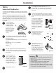
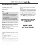
STEP 6
Install Anti-Tip Bracket
To reduce the risk of tipping of the range, the range must be
securedtotheoorwithaproperlyinstalledAnti-TipBracket
(included).
Failure to install the Anti-Tip Bracket will allow the range
to tip over if excessive weight is placed on an open door
or if a child climbs upon it. Serious injury might result from
spilled hot liquids or from the range itself. If range is ever
moved to a different location, the Anti-Tip Bracket must be
re-installed.
u
Contact a qualied
oorcoveringinstaller
for the procedure
of drilling mounting
holes through your
typeofoorcovering.
Retrieve the Anti-Tip
Bracket, two plastic
anchors and two
screws.
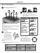
v
You will need additional tools not mentioned in the
“ToolsNeeded”sectiondependingonthetypeof
ooringasfollows:
Concrete/Ceramic Floors:3/16”(4.8mm)Masonry
Drill Bit
Wood Floors:1/8"(3.2mm)DrillBit
Masking Tape
Hammer
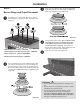
w
The Anti-Tip Bracket is to be installed on the left
rear leg. Follow these steps to secure the range to
theoorbeforemovingtherangeintonalopera-
ting position.
x
Place the template on
oorincabinetopening
(where the range will be
located) so that the left
edge is against cabinet
and top edge is against
rear wall, molding
or cabinet. (See Figure 21)
y
Tape template in place.
U
If countertop is deeper than 25” (63.5 cm),
measure and mark a distance of 25” (63.5 cm) in
from the front of countertop and align template
with mark.
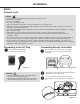
V
TomountAnti-TipBrackettowoodoor,drilltwo
1/8”(3.2mm)pilotholesatthepositionsmarked
on the bracket template. Remove template from the
oor.
To mount Anti-Tip Bracket
to concrete or ceramic
oor,usea3/16”(4.8mm)
masonry drill bit to drill two
pilot holes at the positions
marked on the bracket
template. Remove template
fromtheoor.Tapplastic
anchors into holes with a
hammer.
W
Align Anti-Tip Bracket holes
withholesinoor.Fasten
Anti-Tip Bracket with
screws. (See Figure 23)
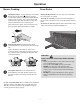
X
Move range close to
opening. Remove shipping
base, cardboard or
hardboard from under range,
if used. Move range into nal
position making sure rear
leveling leg slides into Anti-
Tip Bracket. (See Figure 24)
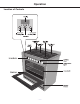
A. ¼" drive ratchet
B. Rear leveling leg
C. Wrench or pliers
D. Front leveling leg
A. Rear leveling leg
B. Front leveling leg
C. Wrench or pliers
A
B
C
D
A
B
C
WARNING
Tip Over Hazard
A child or adult can tip the range and be killed.
Connect anti-tip bracket to rear range foot.
A. ¼" drive ratchet
B. Rear leveling leg
C. Wrench or pliers
D. Front leveling leg
A. Rear leveling leg
B. Front leveling leg
C. Wrench or pliers
A
B
C
D
A
B
C
WARNING
Tip Over Hazard
A child or adult can tip the range and be killed.
Connect anti-tip bracket to rear range foot.
A. ¼" drive ratchet
B. Rear leveling leg
C. Wrench or pliers
D. Front leveling leg
A. Rear leveling leg
B. Front leveling leg
C. Wrench or pliers
A
B
C
D
A
B
C
WARNING
Tip Over Hazard
A child or adult can tip the range and be killed.
Connect anti-tip bracket to rear range foot.
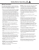
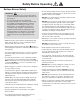
WARNINGS:
• PleasemakesuretoreadALLsafetyprecautionson
pages 4 to 10.
• Usetwoormorepeopletomoveandinstallrange.
• Tip-overHazard.
• Achildoradultcantiptherangeandbekilled.
• Connectanti-tipbrackettorearrangefoot.
• Reconnecttheanti-tipbracket,iftherangeismoved.
• Failuretofollowtheseinstructionscanresultindeath
or serious burns to children and adults.
Installation
Figure 21
Figure 22
Figure 23
Figure 24