
Instructions / Assembly


— 22 —
Installation
STEP 7
Burner Rings and Caps Placement
u
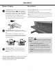
See below for Location of the Burners, as well as
the illustrations of the burner caps and heads. (See
Figure 25
v
Place each burner cap on the matching burner ring.
The cap for each burner has an inner locating ring
which centers the cap correctly on the burner ring.
Be sure that all the burner caps and burner rings are
correctly placed BEFORE using your appliance. (See
Figure 26)
w
Make sure each burner cap is properly aligned and
level, then place the two grates and one triple ring
grate over the burners. (See Figure 27)
x
Test operation
of the electric igniters after the range
and supply line have been carefully checked for
leaks and the range has been connected to the
electrical power (see page 23). Push and turn a
burner until clicking is heard. All ve ignition pins will
spark, but only the open valve will ignite.
y
Insert the oven racks. (See Figure 28)
Figure 28
WARNINGS:
• PleasereadALLsafetyprecautionsonpages4to
10.
• Donotservicethesealedburneryourself.Contact
a qualified service professional.
• Theelectrodeoftheelectronicignitionsystem
is positioned above the surface of the burner
base. Do not remove a burner cap or touch the
electrode of a burner while another is turned on.
Damage or electrical shock may occur.
Figure 25
Figure 26
Figure 27
1.1. riple-ring burnernener ont Left) 18,000 BTU
2.. Semi-rapid b ners (Rear left and right) – 7,000 BTU
3.. Auxiliary b ner (Frontont right) - 5,000
3